Remeshing terrain chunks for hierarchical LODs in C++
Disclaimer: The code in this post is written on version 9.1 of Simplygon. If you encounter this post at a later stage, some of the API calls might have changed. However, the core concepts should still remain valid.
 |
|---|
| Remeshed chunked terrain |
In this example we will discuss how to utilize the remeshing processor for generating a grid of HLOD terrain chunks from a large terrain input geometry. In doing so, we'll go over some basic geometry manipulation, remeshing fundamentals, and advanced usage of some remeshing processor functionality.
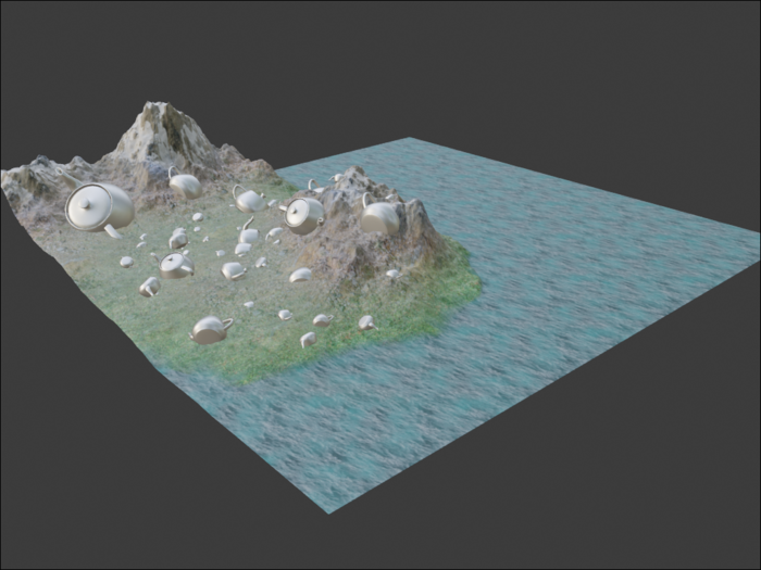
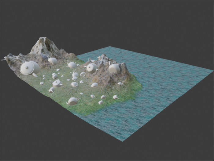
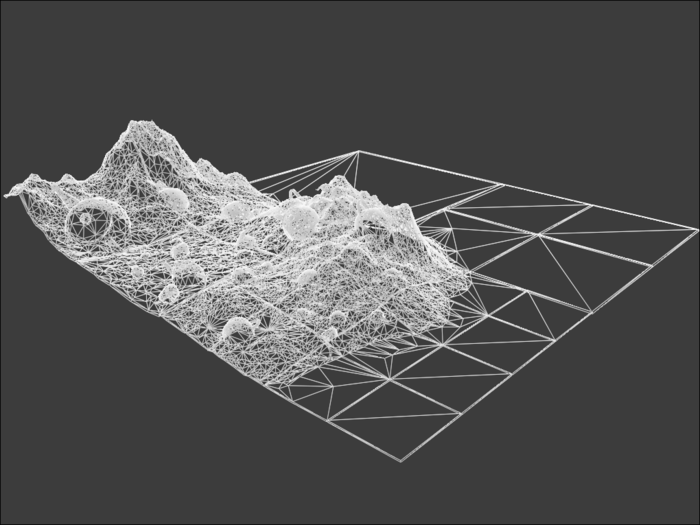
Input scene
The environment we're processing in this example is a basic height-field generated terrain mesh with an assortment of teapots littered around the landscape for some bonus complexity.
 |
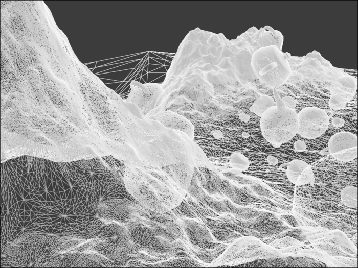 |
|---|---|
| Overview | Wireframe |
Goal
Ideally, what we want as output here are light-weight meshes representing sub-chunks of the world terrain geometry, which can be combined with adjacent different resolution sub-chunks without any seams. There are a couple of different ways one could approach this with the Simplygon toolkit, but here we'll focus on using the remesher.
Potential issues
The RemeshingProcessor, two-manifolds, and clipping planes
The way the remeshing algorithm in Simplygon works is that it essentially "shrink-wraps" the input objects from the outside, generating a new, guaranteed two-manifold mesh. For processing individual objects this is usually great, but it means that for single-sided things like terrain it will generate a layer of geometry for both the top and the bottom. As this will waste both triangle budget and texture space, we want to avoid this. The documentation briefly discusses this problem here. What we need to do here is to utilize the RemeshingProcessors ClippingPlane functionality to effectively build a kind of "aquarium" around the terrain chunk we're remeshing. That way, the remeshing algorithm will only consider the input geometry accessible from the top of the "aquarium", and will only generate new surfaces for those areas. Imagine you fill this hypothetical aquarium with water; only the parts of the original mesh that are in contact with the water will get a surface in the output.
Seams, holes, and artefacts between chunks
Even if we don't use multiple output resolutions of the chunk-grid for different LODs, the border between one chunk its neighbor will not perfectly align. Since the chunks are processed independently and are replaced by entirely new topologies, the vertices along the borders will not line up perfectly, leading to visible cracks for everything but the most trivial input geometry.
A naive but relatively robust method to fix the worst instances of this is to, as a post process, generate a new geometry "skirt" around the remeshed chunk geometry that will intersect and overlap the skirt of the next chunks, creating a visually continuous surface.
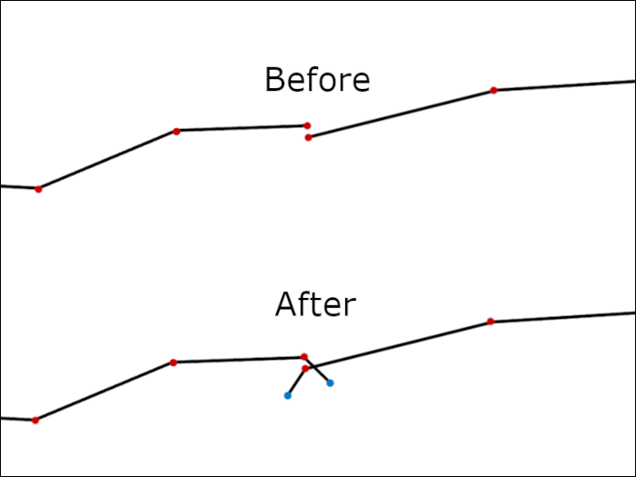 |
|---|
| Chunk border discontinuity after chunks have been independently remeshed |
This does cause some artefacts on borders where the surface normal is facing down (like under an overhang or something like that), but in the general case it works well.
The interaction between OnScreenSize and clipping planes
OnScreenSize is the primary quality setting for the remesher. Conceptually, it means "When the bounding box of the geometry is rendered with this pixel size on-screen, the output LOD should have a maximum geometric error of ~1 pixel". This metric is calculated based on the bounding box of the input geometry, meaning that even if you cull away most of the contents of the scene using clipping planes, the optimization level is still calculated as if the whole scene remained. This can lead to unexpectedly low-resolution results if you expect it to only apply to the remaining, non-culled, geometry.
To avoid this, we need to be aware that the OnScreenSize applies to the bounds of the input scene or selection set, and sanitize the input scene of any geometry you don't want included in the calculation of this quality metric.
Implementation
Main loop
For the purposes of this example, we have an input asset file that contains the entire world we want to chunk up. For each chunk we want to remesh, we follow this rough operation order:
- Import full input world
- Cull all triangles in the input that fall outside the bounds of the active chunk
- Generate "aquarium" clipping planes
- Run remeshing processing
- Generate chunk geometry skirt
- Export
Note that 1-2 here is not really something you should actually do if you have a Simplygon integration, rather you should just load the relevant triangles for the chunk directly. This is largely academic.
Let's look at the implementation:
void RunChunkedTerrainRemeshing( Simplygon::ISimplygon* sg )
{
	std::string inputFilePath = "IslandOfTeapots.glb";

	// Setup chunking
	const uint CHUNKS_X = 4;
	const uint CHUNKS_Z = 4;
	const real GRID_INF[ 3 ] = { -1000.f, -1000.f, -1000.f };
	const real GRID_SUP[ 3 ] = { 1000.f, 1000.f, 1000.f };
	const real GRID_SIZE[ 3 ] = { GRID_SUP[ 0 ] - GRID_INF[ 0 ], GRID_SUP[ 1 ] - GRID_INF[ 1 ], GRID_SUP[ 2 ] - GRID_INF[ 2 ] };
	const real CHUNK_SIZE[ 3 ] = { GRID_SIZE[ 0 ] / CHUNKS_X, GRID_SIZE[ 1 ], GRID_SIZE[ 2 ] / CHUNKS_Z };
	const real CHUNK_HALFSIZE[ 3 ] = { CHUNK_SIZE[ 0 ] / 2, CHUNK_SIZE[ 1 ] / 2, CHUNK_SIZE[ 2 ] / 2 };

	std::string outputBasePath = std::to_string( CHUNKS_X ) + "x" + std::to_string( CHUNKS_Z ) +"chunk_";

	// Remeshing params
	const uint CHUNK_ONSCREENSIZE = 512;
	const uint CHUNK_TEXTURESIZE = 512;

	// This little weird equation essentially means "the length of 20 pixels", since the chunk is CHUNK_ONSCREENSIZE pixels
	const real FLOOR_SAFETY_BUFFER = ( CHUNK_SIZE[ 0 ] / CHUNK_ONSCREENSIZE )*20;

	// Per-chunk, load geometry from disk, cull input triangles outside chunk, setup cutting planes, and remesh
	for( uint z = 0; z < CHUNKS_Z; ++z )
	{
		for( uint x = 0; x < CHUNKS_X; ++x )
		{
			// Need inferior and superior of the AABB to setup clipping planes
			real chunkInf[ 3 ] = {
				GRID_INF[ 0 ] + CHUNK_SIZE[ 0 ] * (real)x,
				GRID_INF[ 1 ],
				GRID_INF[ 2 ] + CHUNK_SIZE[ 2 ] * (real)z };
			real chunkSup[ 3 ] = {
				GRID_INF[ 0 ] + CHUNK_SIZE[ 0 ] * ( real )( x + 1 ),
				GRID_SUP[ 1 ],
				GRID_INF[ 2 ] + CHUNK_SIZE[ 2 ] * ( real )( z + 1 ) };

			// Need center to setup AABB-triangle culling
			real chunkCenter[ 3 ]{};
			for( uint axis = 0; axis < 3; ++axis )
				chunkCenter[ axis ] = chunkInf[ axis ] + CHUNK_HALFSIZE[ axis ];

			// Reload the scene for every chunk, and cull out parts we don't use
			// In real-life scenarios you can likely just load the geometry you need and ignore this inefficient weirdness.
			spSceneImporter imp = sg->CreateSceneImporter();
			imp->SetImportFilePath( inputFilePath.c_str() );
			imp->RunImport();
			spScene scene = imp->GetScene();

			real trianglesChunkInf[ 3 ]{};
			CullTrianglesOutsideBox( scene, trianglesChunkInf, chunkCenter, CHUNK_HALFSIZE, sg );
			chunkInf[ 1 ] = trianglesChunkInf[ 1 ] - FLOOR_SAFETY_BUFFER;

			const uint clipSetId = SetupClippingPlanes( scene, chunkInf, chunkSup, sg );

			spRemeshingPipeline remPipe = sg->CreateRemeshingPipeline();
			auto remSettings = remPipe->GetRemeshingSettings();
			auto mapSettings = remPipe->GetMappingImageSettings();
			auto cullSettings = remPipe->GetGeometryCullingSettings();

			remSettings->SetOnScreenSize( CHUNK_ONSCREENSIZE );
			mapSettings->SetGenerateMappingImage( true );
			mapSettings->GetOutputMaterialSettings( 0 )->SetTextureHeight( CHUNK_TEXTURESIZE );
			mapSettings->GetOutputMaterialSettings( 0 )->SetTextureWidth( CHUNK_TEXTURESIZE );
			cullSettings->SetUseClippingPlanes( true );
			cullSettings->SetClippingPlaneSelectionSetID( clipSetId );

			auto baseColCaster = remPipe->AddMaterialCasterByType( "Color", 0 );
			auto roughnessCaster = remPipe->AddMaterialCasterByType( "Color", 0 );
			auto metalnessCaster = remPipe->AddMaterialCasterByType( "Color", 0 );
			auto normalCaster = spNormalCaster::SafeCast( remPipe->AddMaterialCasterByType( "Normal", 0 ) );
			baseColCaster->GetMaterialCasterSettings()->SetMaterialChannel( SG_MATERIAL_CHANNEL_BASECOLOR );
			roughnessCaster->GetMaterialCasterSettings()->SetMaterialChannel( SG_MATERIAL_CHANNEL_ROUGHNESS );
			metalnessCaster->GetMaterialCasterSettings()->SetMaterialChannel( SG_MATERIAL_CHANNEL_METALNESS );
			normalCaster->GetMaterialCasterSettings()->SetMaterialChannel( SG_MATERIAL_CHANNEL_NORMALS );
			normalCaster->GetNormalCasterSettings()->SetGenerateTangentSpaceNormals( true );

			remPipe->RunScene( scene, EPipelineRunMode::RunInThisProcess );

			AddGeometrySkirts( scene, chunkInf, chunkSup );

			std::string exportPath = outputBasePath + std::to_string( x ) + "_" + std::to_string( z ) + ".glb";
			spSceneExporter exp = sg->CreateSceneExporter();
			exp->SetScene( scene );
			exp->SetExportFilePath( exportPath.c_str() );
			exp->RunExport();
		}
	}
}
Here, a volume is created spanning from GRID_INF to GRID_SUP, and this volume is chunked into 4 sections along the X and Z axes (so Y is our up-axis), generating 4*4 individual remeshed chunks. Our predefined values for GRID_INF and GRID_SUP here fall within the bounds of the imported world terrain, and are used to define the volume we're chunking up. Modifying the CHUNKS_X and CHUNKS_Z here essentially changes the HLOD level we're currently generating. So, for example, this code could be run at 2x2, 4x4, and 8x8 to generate three HLOD levels where chunks can be mixed.
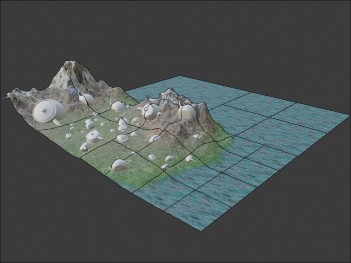
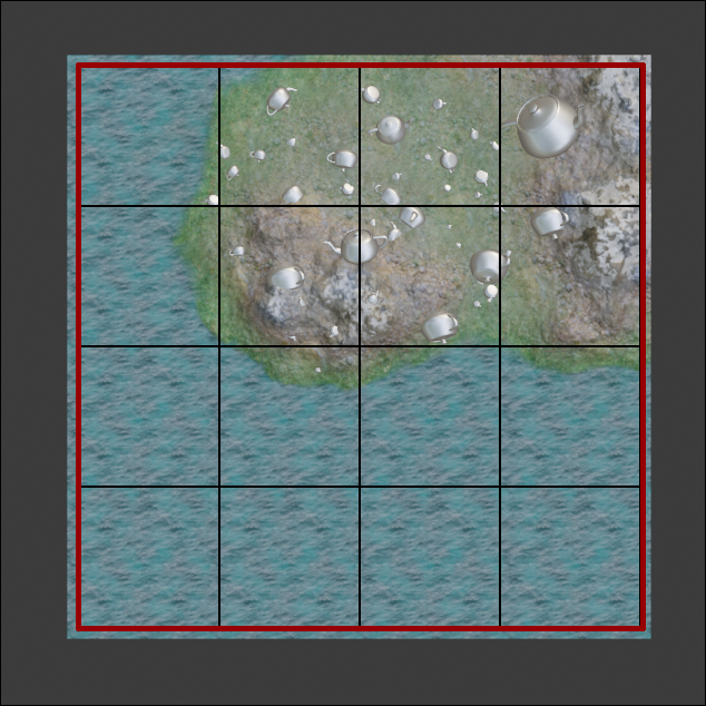 |
|---|
| Chunks created by the 4x4 main loop; the red outline spans from GRID_INF to GRID_SUP, and the black interior lines are borders between chunks. |
FLOOR_SAFETY_BUFFER is used here to move the bottom of the "aquarium" a bit away from the input geometry, so the clipping plane does not interact with triangles we want to keep at the bottom of the chunk. It doesn't work to just define the bottom cutting plane at -INF or something like that, the clipping planes need to be adjacent to the input geometry to be correctly taken into account.
Helper functions called from within this main loop handle the subroutines that were outlined in the steps above.
Input triangle culling
The CullTrianglesOutsideBox function is called from the main loop, and is used to remove all triangles in the input geometry that falls strictly outside our chunk bounds. This is to make sure the OnScreenSize quality metric is applied correctly to only the relevant geometry. This function also calculates the true inferior of the remaining geometry, which is used to setup the bottom of the "aquarium" cutting planes at an appropriate height. For the actual intersection checking we use the triangle-box overlap code by Tomas Akenine Möller, called through the triBoxOverlap function.
void CullTrianglesOutsideBox( spScene scene, real ( &inf )[ 3 ], const real boxCenter[ 3 ], const real boxHalfsize[ 3 ], Simplygon::ISimplygon* sg )
{
	std::vector<spSceneNode> nodeQueue;
	nodeQueue.push_back( scene->GetRootNode() );

	size_t queueIt = 0;
	while( queueIt != nodeQueue.size() )
	{
		auto node = nodeQueue[ queueIt++ ];
		for( uint c = 0; c < node->GetChildCount(); ++c )
			nodeQueue.push_back( node->GetChild( c ) );

		auto mesh = spSceneMesh::SafeCast( node );
		if( !mesh )
			continue;

		auto geom = mesh->GetGeometry();
		if( !geom )
			continue;

		spMatrix4x4 transform = sg->CreateMatrix4x4();
		mesh->EvaluateDefaultGlobalTransformation( transform );
		geom->Transform( transform );

		real triVerts[ 3 ][ 3 ]{};
		auto vertIds = geom->GetVertexIds(); // indices to the verts in the triangles
		auto coords = geom->GetCoords();     // coords of the verts
		for( uint t = 0; t < geom->GetTriangleCount(); ++t )
		{
			for( uint c = 0; c < 3; ++c )
			{
				rid cornerId = t * 3 + c;
				for( uint axis = 0; axis < 3; ++axis )
				{
					rid vertId = vertIds->GetItem( cornerId ) * 3 + axis;
					triVerts[ c ][ axis ] = coords->GetItem( vertIds->GetItem( cornerId ) * 3 + axis );
				}
			}

			if( !triBoxOverlap( boxCenter, boxHalfsize, triVerts ) )
				vertIds->SetItem( t * 3 + 0, -1 ); // Lazy delete, triangle data will be removed by Compact()
		}
		geom->Compact( false );

		geom->CalculateExtents( true );
		spRealData infData = geom->GetInf();
		for( uint axis = 0; axis < 3; ++axis )
		{
			if( infData.GetItem( axis ) < inf[ axis ] )
				inf[ axis ] = infData.GetItem( axis );
		}

		transform->SetToInvert( transform );
		geom->Transform( transform );
	}
}
Note that the coordinates are transformed to world-space before culling so we don't incorrectly cull using the local coords.
Clipping plane setup
Now, using the function SetupClippingPlanes that is called from the main loop, we use the inferior and superior coordinates of the current chunk volume to set up the 5 clipping planes we need to construct the walls and bottom of our "aquarium". The planes are defined by a point and a normal.
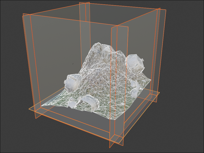 |
|---|
| Cutting planes placed on five sides of the chunk volume, creating a clipping plane "aquarium" |
rid SetupClippingPlanes( spScene scene, const real inf[ 3 ], const real sup[ 3 ], Simplygon::ISimplygon* sg )
{
	// Setup normals for each face
	const real normals[ 6 ][ 3 ] = {
	    { 1.0f, 0.0f, 0.0f },
	    { -1.0f, 0.0f, 0.0f }, // plane at xMin and xMax
	    { 0.0f, 1.0f, 0.0f },
	    { 0.0f, -1.0f, 0.0f }, // plane at yMin and yMax
	    { 0.0f, 0.0f, 1.0f },
	    { 0.0f, 0.0f, -1.0f } // plane at zMin and zMax
	};
	// We skip one plane, the one that would be capping the "top" of our boxed chunk,
	// so the terrain will be shrink-wrapped from the top as we expect.
	// Since this asset has positive Y, we skip the plane at Y max,
	// with a normal pointing towards negative Y. Here, that is normals[3].
	const uint skippedPlaneId = 3;

	spSelectionSet bbSet = sg->CreateSelectionSet();
	for( uint i = 0; i < 6; ++i )
	{
		if( i == skippedPlaneId )
			continue;

		// Set origin to either inf or sup depending on if we're on the negative or positive bounding face
		spScenePlane newPlane{};
		if( i % 2 == 0 )
			newPlane = scene->GetRootNode()->CreateChildPlane( inf, normals[ i ] );
		else
			newPlane = scene->GetRootNode()->CreateChildPlane( sup, normals[ i ] );

		bbSet->AddItem( newPlane->GetNodeGUID() );
	}

	return scene->GetSelectionSetTable()->AddSelectionSet( bbSet );
}
Generating the geometry skirts
Once the remeshing processing has completed, we need to generate new skirt triangles and offset the new vertices down and out from the chunk to create intersections with neighboring chunk geometry. This is handled by the AddGeometrySkirts function that is called from the main loop.
 |
|---|
| Geometry skirts generated by creating new triangles along open edges and offsetting the new vertices, here with exaggerated offset for clarity |
As mentioned earlier, this can cause some artefacts on borders where the surface normal is facing down, but if that turns out to be a big problem one could probably modify this function to have the offset direction take the edge triangle normals into account and offset "inwards" rather than "down and out".
void AddGeometrySkirts( spScene scene, const real inf[ 3 ], const real sup[ 3 ] )
{
	// Get remeshing geometry; new meshes generated by processors are always appended as the last child of root
	auto node = scene->GetRootNode()->GetChild( scene->GetRootNode()->GetChildCount() - 1 );
	auto geom = spSceneMesh::SafeCast( node )->GetGeometry();

	const real offsetLength = ( sup[ 0 ] - inf[ 0 ] ) * 0.01f; // Initial guess for good offset, 1% of chunk x size.

	// This function populates a geometry field that can tell us if we're on an open border, which means we need to add a skirt.
	// The field contains references to neighbor edges you can use to traverse the mesh, or <0 when there is no neighbor.
	geom->DetectEdgeNeighbours();
	auto field = geom->GetUserCornerField( "SgEdgeNeighbours" );
	auto edgeNeighbours = spIntArray::SafeCast( field );

	const uint orgTriCount = geom->GetTriangleCount();
	const uint orgCornerCount = orgTriCount * 3;
	const uint orgVertCount = geom->GetVertexCount();
	auto vertIds = geom->GetVertexIds();
	auto coords = geom->GetCoords();

	std::map<rid, rid> newVertsMap;   // every old border vertex will create a new vertex outside it, maps from old vert->new vert
	std::vector<rid> newTriangles;    // bucket for new triangles, i.e. references to 3 vertex ids per triangle
	std::vector<rid> originalCorners; // bucket for which original corners to copy data from, 3 corners per triangle
	for( rid edgeId = 0; edgeId < (rid)orgCornerCount; ++edgeId )
	{
		if( edgeNeighbours->GetItem( edgeId ) > -1 )
			continue;

		// Found open border
		// Generate two new triangles to act as skirt
		// Two vertices from the original mesh, and two new ones that make up the skirt border
		rid corners[ 2 ] = {
		    edgeId - edgeId % 3 + ( ( edgeId + 1 ) % 3 ),
		    edgeId,
		};
		 //-1 represents new vertices, and will be replaced by the map lookups later
		rid verts[ 4 ] = { vertIds->GetItem( corners[ 0 ] ), vertIds->GetItem( corners[ 1 ] ), -1, -1 };
		for( uint v = 0; v < 2; ++v )
		{
			auto newVertIt = newVertsMap.find( verts[ v ] );
			if( newVertIt != newVertsMap.end() )
				verts[ 3 - v ] = newVertIt->second;
			else
			{
				verts[ 3 - v ] = (rid)orgVertCount + (rid)newVertsMap.size();
				newVertsMap.insert( { verts[ v ], verts[ 3 - v ] } );
			}
		}

		// Add the new quad
		newTriangles.insert( newTriangles.end(), { verts[ 0 ], verts[ 1 ], verts[ 2 ] } );                          // t1
		newTriangles.insert( newTriangles.end(), { verts[ 2 ], verts[ 3 ], verts[ 0 ] } );                          // t2
		originalCorners.insert( originalCorners.end(), { corners[ 0 ], corners[ 1 ], corners[ 1 ] } ); // t1
		originalCorners.insert( originalCorners.end(), { corners[ 1 ], corners[ 0 ], corners[ 0 ] } ); // t2
	}

	// Now we have the topology, write back into the geometrydata, copy vertex and cornerdata to the added elements, and apply coord offsets
	geom->AddTriangles( (uint)newTriangles.size() / 3 );
	geom->AddVertices( (uint)newVertsMap.size() );
	for( uint newTriId = 0; newTriId < newTriangles.size() / 3; ++newTriId )
	{
		// Tri data
		const uint triId = orgTriCount + newTriId;
		const uint copyTriId = originalCorners[ newTriId * 3 + 0 ] / 3; // Triid of the first mapped corner, the corners should be the same.
		geom->CopyTriangle( geom, triId, copyTriId );

		// Corner data
		for( uint c = 0; c < 3; ++c )
		{
			geom->CopyCorner( geom, triId * 3 + c, originalCorners[ newTriId * 3 + c ] );
			vertIds->SetItem( triId * 3 + c, newTriangles[ newTriId * 3 + c ] );
		}
	}
	for( auto newVertIt : newVertsMap )
	{
		// Vertex data
		geom->CopyVertex( geom, newVertIt.second, newVertIt.first );

		// Add offset to new skirt vertices
		AddSkirtOffset( coords, newVertIt.second, inf, sup, offsetLength );
	}
}
This code also calls the AddSkirtOffset function, which determines which border of the chunk we are on, and offsets in the correct direction away from the chunk center.
void AddSkirtOffset( spRealArray coords, rid vId, const real inf[ 3 ], const real sup[ 3 ], const real offsetLength )
{
	const real compareEpsilon = ( sup[ 0 ] - inf[ 0 ] ) / 512.f;
	auto coord = coords->GetTuple( vId );
	real offsetCoord[ 3 ] = { coord[ 0 ], coord[ 1 ] - offsetLength, coord[ 2 ] }; // Always offset down

	// X
	if( fabs( coord[ 0 ] - inf[ 0 ] ) < compareEpsilon )
		offsetCoord[ 0 ] -= offsetLength;
	else if( fabs( coord[ 0 ] - sup[ 0 ] ) < compareEpsilon )
		offsetCoord[ 0 ] += offsetLength;

	// Z
	if( fabs( coord[ 2 ] - inf[ 2 ] ) < compareEpsilon )
		offsetCoord[ 2 ] -= offsetLength;
	else if( fabs( coord[ 2 ] - sup[ 2 ] ) < compareEpsilon )
		offsetCoord[ 2 ] += offsetLength;

	coords->SetTuple( vId, offsetCoord );
}
Results
Here we've generated a 2x2, 4x4, and an 8x8 set of chunked meshes and combined a couple of different LOD levels in this output scene.
 |
|---|
| Standard view |
|
|---|
| Chunks outlined view |
 |
|---|
| Wireframe view |
 |
|---|
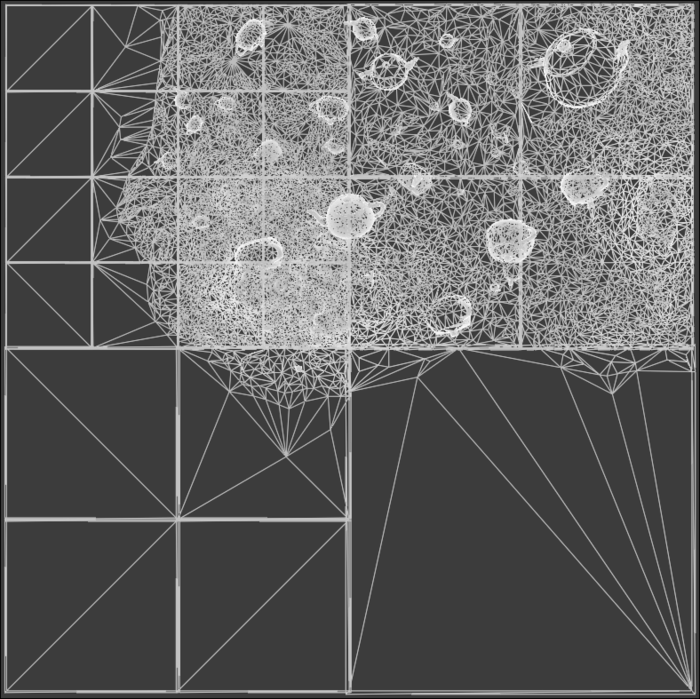
| Top-down wireframe view to see contrasting triangle density between LOD levels |
Full program
Now that we've discussed the individual components, here's the complete source (minus the triangle-box intersection code included here with tribox3.h).
// Copyright (c) Microsoft Corporation.
// Licensed under the MIT license.

#include <string>
#include <map>
#include "SimplygonLoader.h"
#include "tribox3.h"

using namespace Simplygon;
typedef unsigned int uint;

// Main function
static void RunChunkedTerrainRemeshing( Simplygon::ISimplygon* sg );

// Lazy-deletes all triangles in the scene that fall outside a box, and calculates a new inferior for the surviving geometry
static void CullTrianglesOutsideBox( spScene scene, real ( &inf )[ 3 ], const real boxCenter[ 3 ], const real boxHalfsize[ 3 ], Simplygon::ISimplygon* sg );

// Populates the scene with cutting planes based on the geometry input bounding box
static rid SetupClippingPlanes( spScene scene, const real inf[ 3 ], const real sup[ 3 ], Simplygon::ISimplygon* sg );

// Tesselates a new "skirt" around the geometries in the scene
static void AddGeometrySkirts( spScene scene, const real inf[ 3 ], const real sup[ 3 ] );

// Calculates and applied the offset of the new vertices in the geometry skirt
static void AddSkirtOffset( spRealArray coords, rid vId, const real inf[ 3 ], const real sup[ 3 ], const real offsetLength );

int main()
{
	Simplygon::ISimplygon* sg = nullptr;
	Simplygon::EErrorCodes initval = Simplygon::Initialize( &sg );
	if( initval != Simplygon::EErrorCodes::NoError )
	{
		return (int)initval;
	}

	RunChunkedTerrainRemeshing( sg );

	Simplygon::Deinitialize( sg );

	return 0;
}

void RunChunkedTerrainRemeshing( Simplygon::ISimplygon* sg )
{
	std::string inputFilePath = "IslandOfTeapots.glb";

	// Setup chunking
	const uint CHUNKS_X = 4;
	const uint CHUNKS_Z = 4;
	const real GRID_INF[ 3 ] = { -1000.f, -1000.f, -1000.f };
	const real GRID_SUP[ 3 ] = { 1000.f, 1000.f, 1000.f };
	const real GRID_SIZE[ 3 ] = { GRID_SUP[ 0 ] - GRID_INF[ 0 ], GRID_SUP[ 1 ] - GRID_INF[ 1 ], GRID_SUP[ 2 ] - GRID_INF[ 2 ] };
	const real CHUNK_SIZE[ 3 ] = { GRID_SIZE[ 0 ] / CHUNKS_X, GRID_SIZE[ 1 ], GRID_SIZE[ 2 ] / CHUNKS_Z };
	const real CHUNK_HALFSIZE[ 3 ] = { CHUNK_SIZE[ 0 ] / 2, CHUNK_SIZE[ 1 ] / 2, CHUNK_SIZE[ 2 ] / 2 };

	std::string outputBasePath = std::to_string( CHUNKS_X ) + "x" + std::to_string( CHUNKS_Z ) +"chunk_";

	// Remeshing params
	const uint CHUNK_ONSCREENSIZE = 512;
	const uint CHUNK_TEXTURESIZE = 512;

	// This little weird equation essentially means "the length of 20 pixels", since the chunk is CHUNK_ONSCREENSIZE pixels
	const real FLOOR_SAFETY_BUFFER = ( CHUNK_SIZE[ 0 ] / CHUNK_ONSCREENSIZE )*20;

	// Per-chunk, load geometry from disk, cull input triangles outside chunk, setup cutting planes, and remesh
	for( uint z = 0; z < CHUNKS_Z; ++z )
	{
		for( uint x = 0; x < CHUNKS_X; ++x )
		{
			// Need inferior and superior of the AABB to setup clipping planes
			real chunkInf[ 3 ] = {
				GRID_INF[ 0 ] + CHUNK_SIZE[ 0 ] * (real)x,
				GRID_INF[ 1 ],
				GRID_INF[ 2 ] + CHUNK_SIZE[ 2 ] * (real)z };
			real chunkSup[ 3 ] = {
				GRID_INF[ 0 ] + CHUNK_SIZE[ 0 ] * ( real )( x + 1 ),
				GRID_SUP[ 1 ],
				GRID_INF[ 2 ] + CHUNK_SIZE[ 2 ] * ( real )( z + 1 ) };

			// Need center to setup AABB-triangle culling
			real chunkCenter[ 3 ]{};
			for( uint axis = 0; axis < 3; ++axis )
				chunkCenter[ axis ] = chunkInf[ axis ] + CHUNK_HALFSIZE[ axis ];

			// Reload the scene for every chunk, and cull out parts we don't use
			// In real-life scenarios you can likely just load the geometry you need and ignore this inefficient weirdness.
			spSceneImporter imp = sg->CreateSceneImporter();
			imp->SetImportFilePath( inputFilePath.c_str() );
			imp->RunImport();
			spScene scene = imp->GetScene();

			real trianglesChunkInf[ 3 ]{};
			CullTrianglesOutsideBox( scene, trianglesChunkInf, chunkCenter, CHUNK_HALFSIZE, sg );
			chunkInf[ 1 ] = trianglesChunkInf[ 1 ] - FLOOR_SAFETY_BUFFER;

			const uint clipSetId = SetupClippingPlanes( scene, chunkInf, chunkSup, sg );

			spRemeshingPipeline remPipe = sg->CreateRemeshingPipeline();
			auto remSettings = remPipe->GetRemeshingSettings();
			auto mapSettings = remPipe->GetMappingImageSettings();
			auto cullSettings = remPipe->GetGeometryCullingSettings();

			remSettings->SetOnScreenSize( CHUNK_ONSCREENSIZE );
			mapSettings->SetGenerateMappingImage( true );
			mapSettings->GetOutputMaterialSettings( 0 )->SetTextureHeight( CHUNK_TEXTURESIZE );
			mapSettings->GetOutputMaterialSettings( 0 )->SetTextureWidth( CHUNK_TEXTURESIZE );
			cullSettings->SetUseClippingPlanes( true );
			cullSettings->SetClippingPlaneSelectionSetID( clipSetId );

			auto baseColCaster = remPipe->AddMaterialCasterByType( "Color", 0 );
			auto roughnessCaster = remPipe->AddMaterialCasterByType( "Color", 0 );
			auto metalnessCaster = remPipe->AddMaterialCasterByType( "Color", 0 );
			auto normalCaster = spNormalCaster::SafeCast( remPipe->AddMaterialCasterByType( "Normal", 0 ) );
			baseColCaster->GetMaterialCasterSettings()->SetMaterialChannel( SG_MATERIAL_CHANNEL_BASECOLOR );
			roughnessCaster->GetMaterialCasterSettings()->SetMaterialChannel( SG_MATERIAL_CHANNEL_ROUGHNESS );
			metalnessCaster->GetMaterialCasterSettings()->SetMaterialChannel( SG_MATERIAL_CHANNEL_METALNESS );
			normalCaster->GetMaterialCasterSettings()->SetMaterialChannel( SG_MATERIAL_CHANNEL_NORMALS );
			normalCaster->GetNormalCasterSettings()->SetGenerateTangentSpaceNormals( true );

			remPipe->RunScene( scene, EPipelineRunMode::RunInThisProcess );

			AddGeometrySkirts( scene, chunkInf, chunkSup );

			std::string exportPath = outputBasePath + std::to_string( x ) + "_" + std::to_string( z ) + ".glb";
			spSceneExporter exp = sg->CreateSceneExporter();
			exp->SetScene( scene );
			exp->SetExportFilePath( exportPath.c_str() );
			exp->RunExport();
		}
	}
}

void CullTrianglesOutsideBox( spScene scene, real ( &inf )[ 3 ], const real boxCenter[ 3 ], const real boxHalfsize[ 3 ], Simplygon::ISimplygon* sg )
{
	std::vector<spSceneNode> nodeQueue;
	nodeQueue.push_back( scene->GetRootNode() );

	size_t queueIt = 0;
	while( queueIt != nodeQueue.size() )
	{
		auto node = nodeQueue[ queueIt++ ];
		for( uint c = 0; c < node->GetChildCount(); ++c )
			nodeQueue.push_back( node->GetChild( c ) );

		auto mesh = spSceneMesh::SafeCast( node );
		if( !mesh )
			continue;

		auto geom = mesh->GetGeometry();
		if( !geom )
			continue;

		spMatrix4x4 transform = sg->CreateMatrix4x4();
		mesh->EvaluateDefaultGlobalTransformation( transform );
		geom->Transform( transform );

		real triVerts[ 3 ][ 3 ]{};
		auto vertIds = geom->GetVertexIds(); // indices to the verts in the triangles
		auto coords = geom->GetCoords();     // coords of the verts
		for( uint t = 0; t < geom->GetTriangleCount(); ++t )
		{
			for( uint c = 0; c < 3; ++c )
			{
				rid cornerId = t * 3 + c;
				for( uint axis = 0; axis < 3; ++axis )
				{
					rid vertId = vertIds->GetItem( cornerId ) * 3 + axis;
					triVerts[ c ][ axis ] = coords->GetItem( vertIds->GetItem( cornerId ) * 3 + axis );
				}
			}

			if( !triBoxOverlap( boxCenter, boxHalfsize, triVerts ) )
				vertIds->SetItem( t * 3 + 0, -1 ); // Lazy delete, triangle data will be removed by Compact()
		}
		geom->Compact( false );

		geom->CalculateExtents( true );
		spRealData infData = geom->GetInf();
		for( uint axis = 0; axis < 3; ++axis )
		{
			if( infData.GetItem( axis ) < inf[ axis ] )
				inf[ axis ] = infData.GetItem( axis );
		}

		transform->SetToInvert( transform );
		geom->Transform( transform );
	}
}

rid SetupClippingPlanes( spScene scene, const real inf[ 3 ], const real sup[ 3 ], Simplygon::ISimplygon* sg )
{
	// Setup normals for each face
	const real normals[ 6 ][ 3 ] = {
	    { 1.0f, 0.0f, 0.0f },
	    { -1.0f, 0.0f, 0.0f }, // plane at xMin and xMax
	    { 0.0f, 1.0f, 0.0f },
	    { 0.0f, -1.0f, 0.0f }, // plane at yMin and yMax
	    { 0.0f, 0.0f, 1.0f },
	    { 0.0f, 0.0f, -1.0f } // plane at zMin and zMax
	};
	// We skip one plane, the one that would be capping the "top" of our boxed chunk,
	// so the terrain will be shrink-wrapped from the top as we expect.
	// Since this asset has positive Y, we skip the plane at Y max,
	// with a normal pointing towards negative Y. Here, that is normals[3].
	const uint skippedPlaneId = 3;

	spSelectionSet bbSet = sg->CreateSelectionSet();
	for( uint i = 0; i < 6; ++i )
	{
		if( i == skippedPlaneId )
			continue;

		// Set origin to either inf or sup depending on if we're on the negative or positive bounding face
		spScenePlane newPlane{};
		if( i % 2 == 0 )
			newPlane = scene->GetRootNode()->CreateChildPlane( inf, normals[ i ] );
		else
			newPlane = scene->GetRootNode()->CreateChildPlane( sup, normals[ i ] );

		bbSet->AddItem( newPlane->GetNodeGUID() );
	}

	return scene->GetSelectionSetTable()->AddSelectionSet( bbSet );
}

void AddGeometrySkirts( spScene scene, const real inf[ 3 ], const real sup[ 3 ] )
{
	// Get remeshing geometry; new meshes generated by processors are always appended as the last child of root
	auto node = scene->GetRootNode()->GetChild( scene->GetRootNode()->GetChildCount() - 1 );
	auto geom = spSceneMesh::SafeCast( node )->GetGeometry();

	const real offsetLength = ( sup[ 0 ] - inf[ 0 ] ) * 0.01f; // Initial guess for good offset, 1% of chunk x size.

	// This function populates a geometry field that can tell us if we're on an open border, which means we need to add a skirt.
	// The field contains references to neighbor edges you can use to traverse the mesh, or <0 when there is no neighbor.
	geom->DetectEdgeNeighbours();
	auto field = geom->GetUserCornerField( "SgEdgeNeighbours" );
	auto edgeNeighbours = spIntArray::SafeCast( field );

	const uint orgTriCount = geom->GetTriangleCount();
	const uint orgCornerCount = orgTriCount * 3;
	const uint orgVertCount = geom->GetVertexCount();
	auto vertIds = geom->GetVertexIds();
	auto coords = geom->GetCoords();
	std::map<rid, rid> newVertsMap;   // every old border vertex will create a new vertex outside it, maps from old vert->new vert
	std::vector<rid> newTriangles;    // bucket for new triangles, i.e. references to 3 vertex ids per triangle
	std::vector<rid> originalCorners; // bucket for which original corners to copy data from, 3 corners per triangle
	for( rid edgeId = 0; edgeId < (rid)orgCornerCount; ++edgeId )
	{
		if( edgeNeighbours->GetItem( edgeId ) > -1 )
			continue;

		// Found open border
		// Generate two new triangles to act as skirt
		// Two vertices from the original mesh, and two new ones that make up the skirt border
		rid corners[ 2 ] = {
		    edgeId - edgeId % 3 + ( ( edgeId + 1 ) % 3 ),
		    edgeId,
		};
		 //-1 represents new vertices, and will be replaced by the map lookups later
		rid verts[ 4 ] = { vertIds->GetItem( corners[ 0 ] ), vertIds->GetItem( corners[ 1 ] ), -1, -1 };
		for( uint v = 0; v < 2; ++v )
		{
			auto newVertIt = newVertsMap.find( verts[ v ] );
			if( newVertIt != newVertsMap.end() )
				verts[ 3 - v ] = newVertIt->second;
			else
			{
				verts[ 3 - v ] = (rid)orgVertCount + (rid)newVertsMap.size();
				newVertsMap.insert( { verts[ v ], verts[ 3 - v ] } );
			}
		}

		// Add the new quad
		newTriangles.insert( newTriangles.end(), { verts[ 0 ], verts[ 1 ], verts[ 2 ] } );                          // t1
		newTriangles.insert( newTriangles.end(), { verts[ 2 ], verts[ 3 ], verts[ 0 ] } );                          // t2
		originalCorners.insert( originalCorners.end(), { corners[ 0 ], corners[ 1 ], corners[ 1 ] } ); // t1
		originalCorners.insert( originalCorners.end(), { corners[ 1 ], corners[ 0 ], corners[ 0 ] } ); // t2
	}

	// Now we have the topology, write back into the geometrydata, copy vertex and cornerdata to the added elements, and apply coord offsets
	geom->AddTriangles( (uint)newTriangles.size() / 3 );
	geom->AddVertices( (uint)newVertsMap.size() );
	for( uint newTriId = 0; newTriId < newTriangles.size() / 3; ++newTriId )
	{
		// Tri data
		const uint triId = orgTriCount + newTriId;
		const uint copyTriId = originalCorners[ newTriId * 3 + 0 ] / 3; // Triid of the first mapped corner, the corners should be the same.
		geom->CopyTriangle( geom, triId, copyTriId );

		// Corner data
		for( uint c = 0; c < 3; ++c )
		{
			geom->CopyCorner( geom, triId * 3 + c, originalCorners[ newTriId * 3 + c ] );
			vertIds->SetItem( triId * 3 + c, newTriangles[ newTriId * 3 + c ] );
		}
	}
	for( auto newVertIt : newVertsMap )
	{
		// Vertex data
		geom->CopyVertex( geom, newVertIt.second, newVertIt.first );

		// Add offset to new skirt vertices
		AddSkirtOffset( coords, newVertIt.second, inf, sup, offsetLength );
	}
}

void AddSkirtOffset( spRealArray coords, rid vId, const real inf[ 3 ], const real sup[ 3 ], const real offsetLength )
{
	const real compareEpsilon = ( sup[ 0 ] - inf[ 0 ] ) / 512.f;
	auto coord = coords->GetTuple( vId );
	real offsetCoord[ 3 ] = { coord[ 0 ], coord[ 1 ] - offsetLength, coord[ 2 ] }; // Always offset down

	// X
	if( fabs( coord[ 0 ] - inf[ 0 ] ) < compareEpsilon )
		offsetCoord[ 0 ] -= offsetLength;
	else if( fabs( coord[ 0 ] - sup[ 0 ] ) < compareEpsilon )
		offsetCoord[ 0 ] += offsetLength;

	// Z
	if( fabs( coord[ 2 ] - inf[ 2 ] ) < compareEpsilon )
		offsetCoord[ 2 ] -= offsetLength;
	else if( fabs( coord[ 2 ] - sup[ 2 ] ) < compareEpsilon )
		offsetCoord[ 2 ] += offsetLength;

	coords->SetTuple( vId, offsetCoord );
}