Using your own shaders for material baking with Compute Casting
Written by Jesper Tingvall, Product Expert, Simplygon
Disclaimer: The code in this post is written using version 10.2.5200.0 of Simplygon. If you encounter this post at a later stage, some of the API calls might have changed. However, the core concepts should still remain valid.
Introduction
Today we will look at how to create proxies for object with custom shaders. We are going to use compute casters in combination with scene descriptions serialized to xml files to create a batch processor indented to process HLOD meshes. We'll also cover clipping planes.
Prerequisites
This example will use the Simplygon Python API, but the same concepts can be applied to all other integrations of the Simplygon API. Our shaders are specified in HLSL but it is also possible to use GLSL. Compute casters can be used with any pipeline using material casting.
Problem to solve
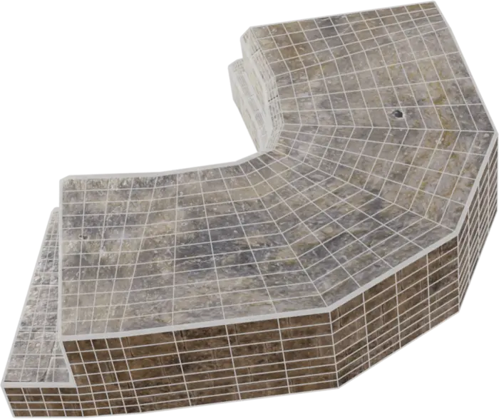
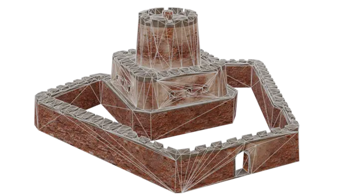
We want to create a distant representation for a collection of objects. The assets have a specific shader blending between different texture described in a *.hlsl shader.
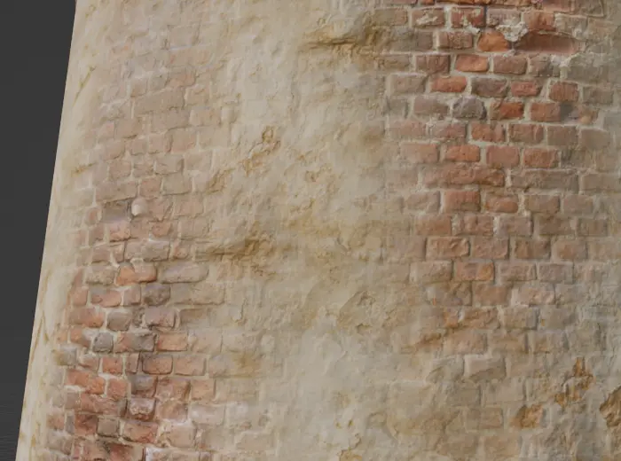
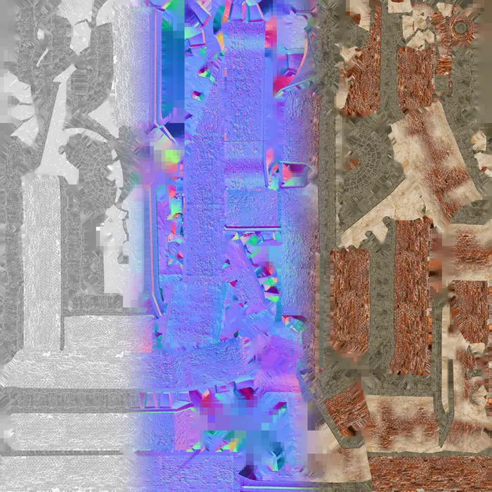
In this blog we are going to use this modular fort asset as well as Medieval Wall 01 and Castle Brick Broken 06 textures. The assets has been adapted to suit topic of the blog better.
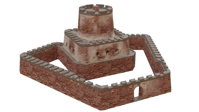
The assets are saved with normals, tangens and bitangents vertex attributes. This data is needed to cast the tangent-space normal map. If your input assets does not contain this data use a Tangent Calculator. How this is done can be seen in this compute casting with scene description example.
Solution
We are going to use a remeshing pipeline to create a low poly representation of our scene. To this remeshing we then are going to cast a material using our new compute caster. To avoid having to set up compute casters in code for each asset we are going to use scene descriptors to serialize the material description for each file.
We are also going to use a clipping plane as our scene lacks geometry at the bottom.
The end result will be a batch processor which as input takes a folder with models, textures, shaders and their material descriptions. After processing them it outputs them into another folder.
The batch script is intended to run in this folder structure. The input folder contains all *.fbx assets, each with a corresponding scene descriptor *.xml file. All textures are in the textures folder and shaders in shaders folder. Result of processing will be found in output folder.
input/
|--> textures/
|    |--> textureA.png
|    |--> textureB.png
|--> shaders/
|    |--> shader1.hlsl
|    |--> shader2.hlsl
|--> assetA.fbx
|--> assetA.xml
|--> assetB.fbx
|--> assetB.xml
output/
|--> textures/
|    |--> assetA_diffuse.png
|--> assetA.fbx
ComputeCaster.py
Remeshing pipeline
Let us start by creating a remeshing pipeline. As we are going to use material casting we need to also create a mapping image with tangent and texture coordinates. We expose screen size and texture size from the function so we can use them control the quality of our proxies.
def create_pipline(sg: Simplygon.ISimplygon, screen_size : int, texture_size : int) -> Simplygon.spRemeshingPipeline:
    """Create remeshing pipeline with specified quality settings."""

    pipeline = sg.CreateRemeshingPipeline()
    settings = pipeline.GetRemeshingSettings()
    settings.SetOnScreenSize(screen_size)

    mapping_image_settings = pipeline.GetMappingImageSettings()
    mapping_image_settings.SetGenerateMappingImage(True)
    mapping_image_settings.SetGenerateTangents(True)
    mapping_image_settings.SetGenerateTexCoords(True)

    material_output_settings = mapping_image_settings.GetOutputMaterialSettings(0)
    material_output_settings.SetTextureHeight(texture_size)
    material_output_settings.SetTextureWidth(texture_size)
    mapping_image_settings.SetTexCoordName("MaterialLOD")

    return pipeline
Clipping planes
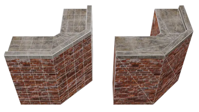
Our assets does not have any geometry on the bottom. That means if f we would remesh the asset as it is we would get an output that is two sided. In essence we would waste half of the texture space and get double geometry. To not get this we will use clipping planes. This can also be solved with clipping geometry which would be suitable if we had a terrain to clip against.
Let us start by creating a function which creates a clipping plane. Clipping is done via selection sets. We start by creating one using CreateSelectionSet. Then we can use CreateChildPlane on our scene's root node to add a ScenePlane. It requires a position and normal which we have as input to our function. Lastly we assign the plane to our selection set and add it to our scene.
def create_clipping_plane(sg : Simplygon.ISimplygon, scene : Simplygon.spScene, position : list[float], normal : list[float]) -> int:
    """Create a plane and assign it to selection set intended to be used as clipping plane. Returns ID of selection set."""

    selection_set = sg.CreateSelectionSet()

    plane = scene.GetRootNode().CreateChildPlane( position, normal)
    selection_set.AddItem( plane.GetNodeGUID() )
    return scene.GetSelectionSetTable().AddSelectionSet( selection_set )
Once we have a clipping plane in our scene we can use it our remeshing pipeline. To do this we enable UseClippingPlanes and set ClippingPlaneSelectionSetID to the selection set containing the plane. It is possible to assign multiple planes to the same selection set.
def use_clipping_plane(pipeline : Simplygon.spRemeshingPipeline, clipping_plane_id : int):
    """Use specified clipping plane to cull away geometry."""

    culling_settings = pipeline.GetGeometryCullingSettings()
    culling_settings.SetClippingPlaneSelectionSetID(clipping_plane_id)
    culling_settings.SetUseClippingPlanes(True)
We use the functions above to create a clipping plane and use it in our remeshing pipeline. The plane is placed so it cuts away everything underneath Y-axis 0. We achieve this by placing the plane in origo [0, 0, 0] and making it's normal pointing upwards [0, 1, 0]. Depending on engine or DCC tools you might have different coordinate system.
# Create clipping plane
clipping_plane_position = [ 0.0, 0.0, 0.0]
clipping_plane_normal = [ 0.0, 1.0, 0.0]
clipping_plane_id = create_clipping_plane(sg, scene, clipping_plane_position, clipping_plane_normal)

# Tell remesher to use clipping plane
use_clipping_plane(pipeline, clipping_plane_id)
After processing our asset with a clipping plane it does not become double sided. Instead it is hollow without a bottom just like our original asset.
Compute casters
To bake materials specified using shader code we will use a compute caster. As this require a little bit more setup then our other casters it can be worth discussing why we would want to use it. Some major reasons are.
- The major benefit of compute casters is that in compute casters we can cast whatever that can be expressed in shader code.
- As the shaders used for compute casting can be generated from shader code used in the game engine this significantly decreases the development costs of using material baking with custom shaders. Developers no longer have to support one set of shaders used for runtime rendering and one set of shaders for baking proxies.
- Compute casters have full pipeline support and can be run in new process or distributed. I can be greatly accelerated by systems having a GPU but works as well on CPU-only systems.
The example we are using in this blog, an asset with a simple vertex blended shader, is also possible to optimize using Simplygon Shading networks. But we can see that if we want to optimize an asset with a non trivial shader then it would be a major hurdle to create a shading network for it.
Now let's start to create our compute casters. As the description of our scene's materials is will be done using scene descriptor *.xml files all we need to specify per caster is MaterialChannel and OutputColorSpace. We will also specify where to output the file using OutputFilePath as well as file format with OutputImageFileFormat. We do this is because we want the batch script to output textures to the output folder structure rather then include it in the output scene.
def create_compute_caster(sg : Simplygon.ISimplygon, channel_name : str, color_space, output_path : str) -> Simplygon.spComputeCaster:
    """Create compute caster for specified channel and color space."""

    print(f"Creating compute caster for {channel_name}")
    caster = sg.CreateComputeCaster()
    caster.SetOutputFilePath(output_path)

    caster_settings = caster.GetComputeCasterSettings()
    caster_settings.SetMaterialChannel(channel_name)
    caster_settings.SetOutputColorSpace(color_space)
    caster_settings.SetOutputImageFileFormat( Simplygon.EImageOutputFormat_PNG )
    return caster
We can now create a list of the materials we want to cast. This is specified as a tuple of channel name and color space to use.
# Channels to cast
# Tuple of string with material name and output color space
MATERIAL_CHANNELS = [("Diffuse", Simplygon.EImageColorSpace_sRGB),
                     ("Roughness", Simplygon.EImageColorSpace_Linear),
                     ("Normals", Simplygon.EImageColorSpace_Linear)]
We can then iterate through our list of material channels, create compute casters for each one of them and add to our remeshing pipeline.
# Add compute casters for all material channels
for channel in MATERIAL_CHANNELS:
    compute_caster = create_compute_caster(sg, channel[0], channel[1], f"{OUTPUT_TEXTURE_FOLDER}/{asset_name}_{channel[0]}" )
    pipeline.AddMaterialCaster( compute_caster, 0 )
Serialized scene descriptor
It is possible to set up all settings per material for our compute caster using code, but it is quite cumbersome and asset specific. What we instead are going to to is save this as a *.xml file per asset. Scene descriptors enables us to describe each asset's material and textures without having to introduce a lot of asset specific code in our batch processor. The scene description can easily be loaded and applied to a scene using this code.
In this example we are going to create this file by hand, but in a production pipeline we suggest to create this file programmatically. We have build in functions for serializing compute caster scene description to a *.xml file, but it is also possible to use your own code for this.
# Load material description file
scene_description_serializer = sg.CreateMaterialEvaluationShaderSerializer()
scene_description_serializer.LoadSceneMaterialEvaluationShadersFromFile(material_description_file, scene)
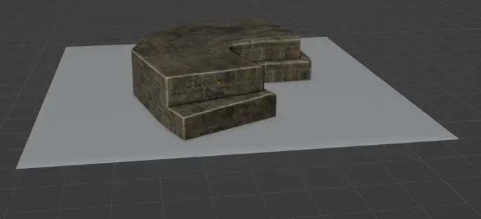
Asset with one simple material
Let us start with the most simple asset in our asset pack. It has just one material consisting of a diffuse channel, roughness channel and normal channel. There is no texture blending going on in the material shader.
Let us create a scene descriptor file for it. We will start by adding a texture table to our scene descriptor specifying which textures paths we have in our scene and the color space for them. If all textures are already set up in your scene this is not needed. This is just a convenient way of appending texture references to our scene.
<?xml version="2.0" encoding="UTF-8"?>

<Scene>

    <TextureTable>
        <Texture Name="modular_fort_01_trim_diff_2k" FilePath="input/textures/modular_fort_01_trim_diff_2k.png"  ColorSpace="sRGB"/>
        <Texture Name="modular_fort_01_trim_nor_gl_2k" FilePath="input/textures/modular_fort_01_trim_nor_gl_2k.png" ColorSpace="Linear"/>
        <Texture Name="modular_fort_01_trim_rough_2k" FilePath="input/textures/modular_fort_01_trim_rough_2k.png" ColorSpace="Linear"/>
    </TextureTable>
Now let us set up a material table describing all materials in the file. This is something only used for compute casting and will not be references by for example our old color caster. In this assets case we only have one.
First we need to specify which shader file to use when performing compute casting.
	<MaterialTable>
        <Material Name="modular_fort_01_trim_1">
            <MaterialEvaluationShader Version="0.4.0" ShaderLanguage="HLSL" ShaderFilePath="shaders/BasicMaterial.hlsl">
We then need to specify all vertex attributes we use in our shader. In our case we use TexCoords, Tangent, Bitangent and Normal. If we have multiple attributes of the same type we can reference them by name using FieldName. If no name is specified it is implied that we refer to the first field of that type.
                <Attribute Name="TexCoord" FieldType="TexCoords" FieldName="0" FieldFormat="F32vec2"/>
                <Attribute Name="Tangent" FieldType="Tangents" FieldFormat="F32vec3"/>
                <Attribute Name="Bitangent" FieldType="Bitangents" FieldFormat="F32vec3"/>
                <Attribute Name="Normal" FieldType="Normals" FieldFormat="F32vec3"/>
We then specify which shader function that corresponds to which material channel by creating EvaluationFunctions and specify the shader function name in EntryPoint. It is possible you need to introduce some glue functions when using your own shader.
				<EvaluationFunction Channel="Diffuse" EntryPoint="CalculateDiffuseChannel"/>
				<EvaluationFunction Channel="Roughness" EntryPoint="CalculateRoughnessChannel"/>
                <EvaluationFunction Channel="Normals" EntryPoint="CalculateNormalsChannel"/>
Lastly we create one ShaderParameterSamplerState state that specifies the texturing addressing modes. We then reuse it for all ShaderParameterSamplers in which we expose the textures in our scenes texture table to our shader.
                <ShaderParameterSamplerState Name="Sampler2D" MinFilter="Linear" MagFilter="Linear" AddressU="Repeat" AddressV="Repeat" AddressW="Repeat" />

                <ShaderParameterSampler Name="DiffuseTexture" SamplerState="Sampler2D" TextureName="modular_fort_01_trim_diff_2k"/>
                <ShaderParameterSampler Name="RoughnessTexture" SamplerState="Sampler2D" TextureName="modular_fort_01_trim_rough_2k"/>
                <ShaderParameterSampler Name="NormalTexture" SamplerState="Sampler2D" TextureName="modular_fort_01_trim_nor_gl_2k"/>
            </MaterialEvaluationShader>
        </Material>
	</MaterialTable>
</Scene>
That is all for our scene description xml file. Before we continue let's take a step back and look where this fit into our compute casting pipeline.
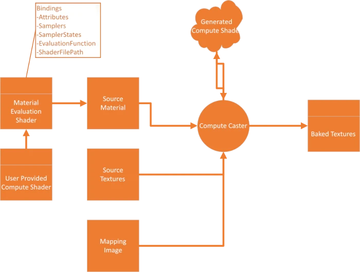
Our compute casted needs several things as input. When we have all pieces in place we can generate a compute shader that is then executed either on the GPU or CPU to generate a texture output. What we have defined so far is following.
- Mapping image that is generated by our remeshing pipeline.
- In our scene description above we specified the binding data used for our Material Evaluation Shader, the data in the white box in the image.
- Our scene description also specified source textures, this could also be done in the input model file directly.
To fully define the source material we are missing one piece; user provided compute shader. Let us look at that next. Like in the case of the scene descriptor file we will in this example write this shader by hand, but suggest that you do this programmatically based on the shader code in your game.
The functions CalculateDiffuseChannel and CalculateRoughnessChannel are very simple. It just samples the texture and outputs it. The sample state of our ShaderParameterSampler can be referenced via [ShaderParameterSamplerName]SamplerState. One thing to notice is that as compute casting is done in a compute shader we do not have access to the Sample function and need to use SampleLevel instead.
// Sample Diffuse texture for diffuse channel

float4 CalculateDiffuseChannel()
{
    float4 color = DiffuseTexture.SampleLevel(DiffuseTextureSamplerState, TexCoord,0);
    return color;
}

// Sample Roughness texture for roughness channel

float4 CalculateRoughnessChannel()
{
    float4 color = RoughnessTexture.SampleLevel(RoughnessTextureSamplerState, TexCoord,0);
    return color;
}
The normal shader looks a bit more intimidating. But fear not, it is very simple. We start by sampling our normal map and remap it from color space (0->1) to vector space (-1 → 1).
float4 CalculateNormalsChannel()
{
    float3 tangentSpaceNormal = (NormalTexture.SampleLevel(NormalTextureSamplerState, TexCoord,0).xyz * 2.0) - 1.0;
After that is done we transform it into object space using Tangent, Bitangent and Normal attributes from our model. These where the fields we exposed earlier in our scene descriptor.
	// transform into an object-space vector
	float3 objectSpaceNormal = 	tangentSpaceNormal.x * normalize(Tangent) +
								tangentSpaceNormal.y * normalize(Bitangent) +
								tangentSpaceNormal.z * normalize(Normal);
We then use the build in variables sg_DestinationTangent, sg_DestinationBitangent and sg_DestinationNormal to transform our normal into our remeshed model's tangent space.
	// transform the object-space vector into the destination tangent space
	tangentSpaceNormal.x = dot( objectSpaceNormal , normalize(sg_DestinationTangent) );
	tangentSpaceNormal.y = dot( objectSpaceNormal , normalize(sg_DestinationBitangent) );
	tangentSpaceNormal.z = dot( objectSpaceNormal , normalize(sg_DestinationNormal) );
Lastly we ensure that our vector is normalized and map it back into color space (0->1).
	// normalize, the tangent basis is not necessarily orthogonal
	tangentSpaceNormal = normalize(tangentSpaceNormal);

	// encode into [0 -> 1] basis and return
	return float4( ((tangentSpaceNormal + 1.0)/2.0) , 1.0);
}
When all that is done we can process thte asset and inspect the output. It looks very good.
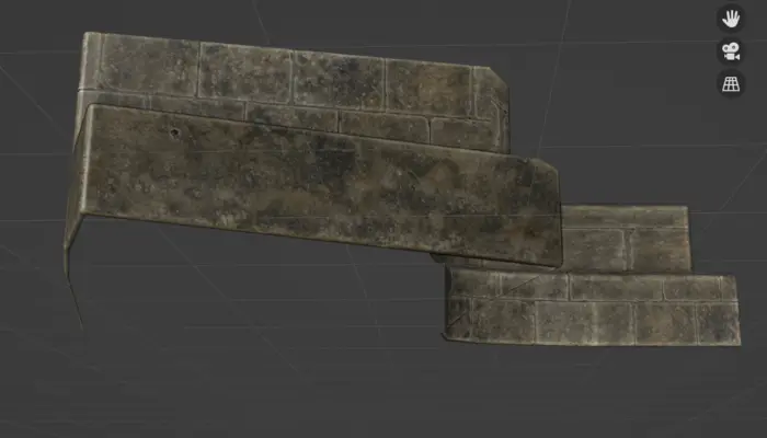
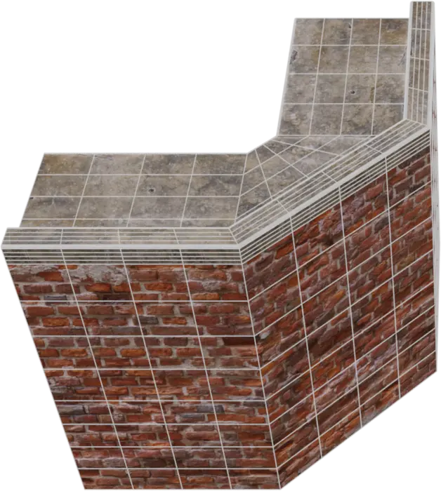
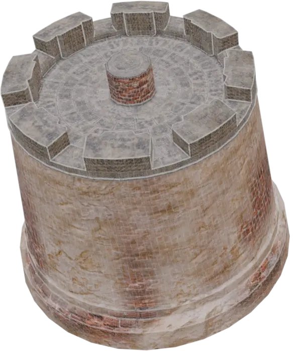
Asset with two simple materials
Now lets try to tackle an asset with two materials on it. We will use the same basic shader so only thing we need to do is create a corresponding scene descriptor file.
First we add all textures we need to our texture table.
<?xml version="1.0" encoding="UTF-8"?>

<Scene>

    <TextureTable>
        <Texture Name="modular_fort_01_trim_diff_2k" FilePath="input/textures/modular_fort_01_trim_diff_2k.png"/>
        <Texture Name="modular_fort_01_trim_nor_gl_2k" FilePath="input/textures/modular_fort_01_trim_nor_gl_2k.png" ColorSpace="Linear"/>
        <Texture Name="modular_fort_01_trim_rough_2k" FilePath="input/textures/modular_fort_01_trim_rough_2k.png" ColorSpace="Linear"/>

        <Texture Name="castle_brick_broken_06_diff_4k" FilePath="input/textures/castle_brick_broken_06_diff_4k.png"/>
        <Texture Name="castle_brick_broken_06_nor_gl_4k" FilePath="input/textures/castle_brick_broken_06_nor_gl_4k.png" ColorSpace="Linear"/>
        <Texture Name="castle_brick_broken_06_rough_4k" FilePath="input/textures/castle_brick_broken_06_rough_4k.png" ColorSpace="Linear"/>
    </TextureTable>
Our material table has now two materials. Both refers to the same shader and the attributes and evaluation functions are identical. Only difference is that ShaderParameterSampler in our second material refers to other textures.
	<MaterialTable>
        <Material Name="modular_fort_01_trim_1">
            <MaterialEvaluationShader Version="0.4.0" ShaderLanguage="HLSL" ShaderFilePath="shaders/BasicMaterial.hlsl">

                <Attribute Name="TexCoord" FieldType="TexCoords" FieldName="0" FieldFormat="F32vec2"/>
                <Attribute Name="Tangent" FieldType="Tangents" FieldFormat="F32vec3"/>
                <Attribute Name="Bitangent" FieldType="Bitangents" FieldFormat="F32vec3"/>
                <Attribute Name="Normal" FieldType="Normals" FieldFormat="F32vec3"/>

				<EvaluationFunction Channel="Diffuse" EntryPoint="CalculateDiffuseChannel"/>
				<EvaluationFunction Channel="Roughness" EntryPoint="CalculateRoughnessChannel"/>
                <EvaluationFunction Channel="Normals" EntryPoint="CalculateNormalsChannel"/>

                <ShaderParameterSamplerState Name="Sampler2D" MinFilter="Linear" MagFilter="Linear" AddressU="Repeat" AddressV="Repeat" AddressW="Repeat" />

                <ShaderParameterSampler Name="DiffuseTexture" SamplerState="Sampler2D" TextureName="modular_fort_01_trim_diff_2k"/>
                <ShaderParameterSampler Name="RoughnessTexture" SamplerState="Sampler2D" TextureName="modular_fort_01_trim_rough_2k"/>
                <ShaderParameterSampler Name="NormalTexture" SamplerState="Sampler2D" TextureName="modular_fort_01_trim_nor_gl_2k"/>
            </MaterialEvaluationShader>
        </Material>

        <Material Name="modular_fort_01_wall_1">
            <MaterialEvaluationShader Version="0.4.0" ShaderLanguage="HLSL" ShaderFilePath="shaders/BasicMaterial.hlsl">

                <Attribute Name="TexCoord" FieldType="TexCoords" FieldName="0" FieldFormat="F32vec2"/>
                <Attribute Name="Tangent" FieldType="Tangents" FieldFormat="F32vec3"/>
                <Attribute Name="Bitangent" FieldType="Bitangents" FieldFormat="F32vec3"/>
                <Attribute Name="Normal" FieldType="Normals" FieldFormat="F32vec3"/>

				<EvaluationFunction Channel="Diffuse" EntryPoint="CalculateDiffuseChannel"/>
				<EvaluationFunction Channel="Roughness" EntryPoint="CalculateRoughnessChannel"/>
                <EvaluationFunction Channel="Normals" EntryPoint="CalculateNormalsChannel"/>

                <ShaderParameterSamplerState Name="Sampler2D" MinFilter="Linear" MagFilter="Linear" AddressU="Repeat" AddressV="Repeat" AddressW="Repeat" />

                <ShaderParameterSampler Name="DiffuseTexture" SamplerState="Sampler2D" TextureName="castle_brick_broken_06_diff_4k"/>
                <ShaderParameterSampler Name="RoughnessTexture" SamplerState="Sampler2D" TextureName="castle_brick_broken_06_rough_4k"/>
                <ShaderParameterSampler Name="NormalTexture" SamplerState="Sampler2D" TextureName="castle_brick_broken_06_nor_gl_4k"/>
            </MaterialEvaluationShader>
        </Material>
	</MaterialTable>
</Scene>
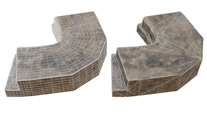
After saving we can now process our asset containing two materials. After processing we get an output with only one material.
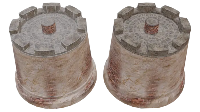
Asset with vertex color blended material
Lastly let's tackle an asset with a little bit more interesting shader. This asset contains two materials, one simple that just outputs the texture and one where we blend between a brick and plaster texture using vertex colors.
One thing to look out for when working with vertex colors is what color space your vertex colors are in. Simplygon works linear color space. If you get strange outputs after casting similar shaders this can be the issue.
Now let's create a scene descriptor for this asset. We add a new MaterialEvaluationShader to our table. In it we refer to our vertex blend shader VertexBlended.hlsl.
<MaterialEvaluationShader Version="0.4.0" ShaderLanguage="HLSL" ShaderFilePath="shaders/VertexBlended.hlsl">
In order to use vertex colors in our shader we need to add it as an attribute. As we do not specify a name we will get the first color field in our asset. Our asset only contains one field of this type so it works well.
<Attribute Name="VertexColor" FieldType="Colors" FieldFormat="F32vec4"/>
We also add a secondary set of ShaderParameterSamplers so we can refer to the secondary texture we want to blend with.
<ShaderParameterSampler Name="DiffuseSecondaryTexture" SamplerState="Sampler2D" TextureName="medieval_wall_01_diff_4k"/>
<ShaderParameterSampler Name="RoughnessSecondaryTexture" SamplerState="Sampler2D" TextureName="medieval_wall_01_rough_4k"/>
<ShaderParameterSampler Name="NormalSecondaryTexture" SamplerState="Sampler2D" TextureName="medieval_wall_01_nor_gl_4k"/>
That is all extra setup for our scene descriptor file. Now let's look at the shader code.
The shader blends between two different textures depending on vertex color's green channel. In CalculateDiffuseChannel and CalculateRoughnessChannel we first sample the secondary texture as well. We then lerp between primary and secondary texture depending on the vertex color attribute we exposed in scene description file.
// Sample two diffuse textures and blend using vertex colors.

float4 CalculateDiffuseChannel()
{
    float4 color = DiffuseTexture.SampleLevel(DiffuseTextureSamplerState, TexCoord,0);
    float4 colorSecondary = DiffuseSecondaryTexture.SampleLevel(DiffuseSecondaryTextureSamplerState, TexCoord,0);
    return lerp(color, colorSecondary, VertexColor.y);
}

// Sample two roughness textures and blend using vertex colors.

float4 CalculateRoughnessChannel()
{
    float4 color = RoughnessTexture.SampleLevel(RoughnessTextureSamplerState, TexCoord,0);
    float4 colorSecondary = RoughnessSecondaryTexture.SampleLevel(RoughnessSecondaryTextureSamplerState, TexCoord,0);
    return lerp(color, colorSecondary, VertexColor.y);
}
We do similar in CalculateNormalsChannel. The only difference from our simple shader is that we sample two normal maps and lerp between the values before transforming into object-space.
float4 CalculateNormalsChannel()
{
    float3 tangentSpaceNormal = (NormalTexture.SampleLevel(NormalTextureSamplerState, TexCoord,0).xyz * 2.0) - 1.0;
    float3 tangentSpaceNormalSecondary = (NormalSecondaryTexture.SampleLevel(NormalSecondaryTextureSamplerState, TexCoord,0).xyz * 2.0) - 1.0;

	// Blend normals
	tangentSpaceNormal = lerp(tangentSpaceNormal, tangentSpaceNormalSecondary, VertexColor.y);

	// transform into an object-space vector
	float3 objectSpaceNormal = 	tangentSpaceNormal.x * normalize(Tangent) +
								tangentSpaceNormal.y * normalize(Bitangent) +
								tangentSpaceNormal.z * normalize(Normal);

    ...
After remeshing we get following output. We can see that Simplygon understands the shader we provided we can use it to bake the material to a proxy.
Result
Now we have processed individual parts of our fort. Let's try to process the entire fort into a model suitable for distant viewing. As the model is build from individual parts there is a lot of face on inside where the parts connect. It would be ideal to remove these.
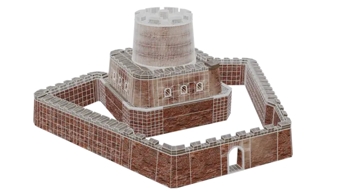
After processing the asset with our batch script we get this output. While the original model was quite low poly in some parts, we have saved a lot of triangles as well as having no internal faces causing overdraw.
Instead of 9 texture references we now only have 3; one diffuse texture, one roughness texture and one normal map. The proxy can be rendered with a simple shader that just samples them all. This is another benefit of compute casters, it allows you to simplify complex shaders. In essence trading shader complexity for texture memory.
After processing our asset we get a low poly representation suitable for distant viewing. We can easily change on screen size and texture size to either increase quality, enabling us to switch to the LOD earlier, or optimize even further.
| Model | Triangle count | Material count | Texture references |
|---|---|---|---|
| Original | 138 k | 2 | 9 x 4k textures |
| Remeshed proxy (500 pixels) | 2 k | 1 | 3 x 2k textures |
Closing words
Compute casters is a new exciting feature and we have already seen great adoption from customers. Compute casters gives you full control of material baking. It enables you to use the same shaders you render your game with for optimizing your game. We are going to put significant focus on compute casters in future releases of Simplygon.
Compute casters can not only be used for remeshing, but any other pipeline where material baking is used. For example, It can be used for distant LODs for skinned characters as well, simplifying you skin shaders and significantly improving draw calls.
Complete scripts
ComputeCasting.py
# Copyright (c) Microsoft Corporation.
# Licensed under the MIT License.

import gc
import os

from simplygon10 import simplygon_loader
from simplygon10 import Simplygon

# Quality settings
SCREEN_SIZE = 500
TEXTURE_RESOLUTION = 1024

# Channels to cast
# Tuple of string with material name and output color space
MATERIAL_CHANNELS = [("Diffuse", Simplygon.EImageColorSpace_sRGB),
                     ("Roughness", Simplygon.EImageColorSpace_Linear),
                     ("Normals", Simplygon.EImageColorSpace_Linear)]

# Output settings
OUTPUT_FOLDER = "output"
OUTPUT_TEXTURE_FOLDER = f"{OUTPUT_FOLDER}/textures"

# Input settings
INPUT_FOLDER = "input"
FILE_ENDING = ".fbx"


def load_scene(sg: Simplygon.ISimplygon, path: str) -> Simplygon.spScene:
    """Load scene from path and return a Simplygon scene."""

    scene_importer = sg.CreateSceneImporter()
    scene_importer.SetImportFilePath(path)

    import_result = scene_importer.Run()
    if Simplygon.Failed(import_result):
        raise Exception('Failed to load scene.')

    scene = scene_importer.GetScene()
    return scene


def save_scene(sg: Simplygon.ISimplygon, sgScene: Simplygon.spScene, path: str):
    """Save scene to path."""

    scene_exporter = sg.CreateSceneExporter()
    scene_exporter.SetExportFilePath(path)
    scene_exporter.SetScene(sgScene)

    print (f"Saving {path}...")

    export_result = scene_exporter.Run()
    if Simplygon.Failed(export_result):
        raise Exception('Failed to save scene.')


def use_clipping_plane(pipeline : Simplygon.spRemeshingPipeline, clipping_plane_id : int):
    """Use specified clipping plane to cull away geometry."""

    culling_settings = pipeline.GetGeometryCullingSettings()
    culling_settings.SetClippingPlaneSelectionSetID(clipping_plane_id)
    culling_settings.SetUseClippingPlanes(True)


def create_pipline(sg: Simplygon.ISimplygon, screen_size : int, texture_size : int) -> Simplygon.spRemeshingPipeline:
    """Create remeshing pipeline with specified quality settings."""

    pipeline = sg.CreateRemeshingPipeline()
    settings = pipeline.GetRemeshingSettings()
    settings.SetOnScreenSize(screen_size)

    mapping_image_settings = pipeline.GetMappingImageSettings()
    mapping_image_settings.SetGenerateMappingImage(True)
    mapping_image_settings.SetGenerateTangents(True)
    mapping_image_settings.SetGenerateTexCoords(True)

    material_output_settings = mapping_image_settings.GetOutputMaterialSettings(0)
    material_output_settings.SetTextureHeight(texture_size)
    material_output_settings.SetTextureWidth(texture_size)
    mapping_image_settings.SetTexCoordName("MaterialLOD")

    return pipeline


def create_compute_caster(sg : Simplygon.ISimplygon, channel_name : str, color_space, output_path : str) -> Simplygon.spComputeCaster:
    """Create compute caster for specified channel and color space."""

    print(f"Creating compute caster for {channel_name}")
    caster = sg.CreateComputeCaster()
    caster.SetOutputFilePath(output_path)

    caster_settings = caster.GetComputeCasterSettings()
    caster_settings.SetMaterialChannel(channel_name)
    caster_settings.SetOutputColorSpace(color_space)
    caster_settings.SetOutputImageFileFormat( Simplygon.EImageOutputFormat_PNG )
    return caster


def remesh_asset(sg: Simplygon.ISimplygon, input_asset : str, asset_name : str):
    """Remesh specified asset and use compute casters to transfer materials using serialized material description."""

    # Load scene
    print(f"Loading {input_asset}")
    scene = load_scene(sg, input_asset)

    # Load material description file
    material_description_file = f"{INPUT_FOLDER}/{asset_name}.xml"
    print(f"Load scene material description from {material_description_file}")
    scene_description_serializer = sg.CreateMaterialEvaluationShaderSerializer()
    scene_description_serializer.LoadSceneMaterialEvaluationShadersFromFile(material_description_file, scene)

    # Create remeshing pipeline
    pipeline = create_pipline(sg, SCREEN_SIZE, TEXTURE_RESOLUTION)

    # Create clipping plane
    clipping_plane_position = [ 0.0, 0.0, 0.0]
    clipping_plane_normal = [ 0.0, 1.0, 0.0]
    clipping_plane_id = create_clipping_plane(sg, scene, clipping_plane_position, clipping_plane_normal)

    # Tell remesher to use clipping plane
    use_clipping_plane(pipeline, clipping_plane_id)

    # Add compute casters for all material channels
    for channel in MATERIAL_CHANNELS:
        compute_caster = create_compute_caster(sg, channel[0], channel[1], f"{OUTPUT_TEXTURE_FOLDER}/{asset_name}_{channel[0]}" )
        pipeline.AddMaterialCaster( compute_caster, 0 )

    # Perform remeshing and material casting
    print("Performing optimization...")
    pipeline.RunScene(scene, Simplygon.EPipelineRunMode_RunInThisProcess)

    # Check if we recieved any errors
    print("Check log for any warnings or errors.")
    check_log(sg)

    # Since we output textures from material casters we clean texture table before saving the scenes.
    # Otherwise we (depending on output file format) get the same texture twice on hard drive.
    scene.GetTextureTable().Clear()

    # Save scene
    save_scene(sg, scene, f"{OUTPUT_FOLDER}/{asset_name}{FILE_ENDING}")


def create_clipping_plane(sg : Simplygon.ISimplygon, scene : Simplygon.spScene, position : list[float], normal : list[float]) -> int:
    """Create a plane and assign it to selection set intended to be used as clipping plane. Returns ID of selection set."""

    selection_set = sg.CreateSelectionSet()

    plane = scene.GetRootNode().CreateChildPlane( position, normal)
    selection_set.AddItem( plane.GetNodeGUID() )
    return scene.GetSelectionSetTable().AddSelectionSet( selection_set )


def check_log(sg: Simplygon.ISimplygon):
    """Outputs any errors or warnings from Simplygon."""

    # Check if any errors occurred.
    has_errors = sg.ErrorOccurred()
    if has_errors:
        errors = sg.CreateStringArray()
        sg.GetErrorMessages(errors)
        error_count = errors.GetItemCount()
        if error_count > 0:
            print('CheckLog: Errors:')
            for error_index in range(error_count):
                error_message = errors.GetItem(error_index)
                print(error_message)
            sg.ClearErrorMessages()
    else:
        print('CheckLog: No errors.')

    # Check if any warnings occurred.
    has_warnings = sg.WarningOccurred()
    if has_warnings:
        warnings = sg.CreateStringArray()
        sg.GetWarningMessages(warnings)
        warning_count = warnings.GetItemCount()
        if warning_count > 0:
            print('CheckLog: Warnings:')
            for warning_index in range(warning_count):
                warning_message = warnings.GetItem(warning_index)
                print(warning_message)
            sg.ClearWarningMessages()
    else:
        print('CheckLog: No warnings.')

    # Error out if Simplygon has errors.
    if has_errors:
        raise Exception('Processing failed with an error')


def process_asset(asset : str):
    """Initialize Simplygon and process asset."""

    asset_name = asset.replace(FILE_ENDING, "")

    sg = simplygon_loader.init_simplygon()
    if sg is None:
        exit(Simplygon.GetLastInitializationError())

    remesh_asset(sg, f"{INPUT_FOLDER}/{asset}", asset_name)


if __name__ == '__main__':
    for asset in os.listdir(INPUT_FOLDER):
        if FILE_ENDING in asset:
            process_asset(asset)
            gc.collect()
BasicMaterial.hlsl
// Sample Diffuse texture for diffuse channel

float4 CalculateDiffuseChannel()
{
    float4 color = DiffuseTexture.SampleLevel(DiffuseTextureSamplerState, TexCoord,0);
    return color;
}

// Sample Roughness texture for roughness channel

float4 CalculateRoughnessChannel()
{
    float4 color = RoughnessTexture.SampleLevel(RoughnessTextureSamplerState, TexCoord,0);
    return color;
}

// The CalculateNormalsChannel calculates the per-texel normals of the output tangent-space normal map. It starts by sampling the input
// tangent-space normal map of the input geometry, and transforms the normal into object-space coordinates. It then uses the generated
// destination tangent basis vectors to transform the normal vector into the output tangent-space.

float4 CalculateNormalsChannel()
{
    float3 tangentSpaceNormal = (NormalTexture.SampleLevel(NormalTextureSamplerState, TexCoord,0).xyz * 2.0) - 1.0;

	// transform into an object-space vector
	float3 objectSpaceNormal = 	tangentSpaceNormal.x * normalize(Tangent) +
								tangentSpaceNormal.y * normalize(Bitangent) +
								tangentSpaceNormal.z * normalize(Normal);

	// transform the object-space vector into the destination tangent space
	tangentSpaceNormal.x = dot( objectSpaceNormal , normalize(sg_DestinationTangent) );
	tangentSpaceNormal.y = dot( objectSpaceNormal , normalize(sg_DestinationBitangent) );
	tangentSpaceNormal.z = dot( objectSpaceNormal , normalize(sg_DestinationNormal) );

	// normalize, the tangent basis is not necessarily orthogonal
	tangentSpaceNormal = normalize(tangentSpaceNormal);

	// encode into [0 -> 1] basis and return
	return float4( ((tangentSpaceNormal + 1.0)/2.0) , 1.0);
}
VertexBlended.hlsl
// Sample two diffuse textures and blend using vertex colors.

float4 CalculateDiffuseChannel()
{
    float4 color = DiffuseTexture.SampleLevel(DiffuseTextureSamplerState, TexCoord,0);
    float4 colorSecondary = DiffuseSecondaryTexture.SampleLevel(DiffuseSecondaryTextureSamplerState, TexCoord,0);
    return lerp(color, colorSecondary, VertexColor.y);
}

// Sample two roughness textures and blend using vertex colors.

float4 CalculateRoughnessChannel()
{
    float4 color = RoughnessTexture.SampleLevel(RoughnessTextureSamplerState, TexCoord,0);
    float4 colorSecondary = RoughnessSecondaryTexture.SampleLevel(RoughnessSecondaryTextureSamplerState, TexCoord,0);
    return lerp(color, colorSecondary, VertexColor.y);
}

// The CalculateNormalsChannel calculates the per-texel normals of the output tangent-space normal map. It starts by sampling the input
// tangent-space normal map of the input geometry, blend between two normals maps and transforms the normal into object-space coordinates. It then uses the generated
// destination tangent basis vectors to transform the normal vector into the output tangent-space.

float4 CalculateNormalsChannel()
{
    float3 tangentSpaceNormal = (NormalTexture.SampleLevel(NormalTextureSamplerState, TexCoord,0).xyz * 2.0) - 1.0;
    float3 tangentSpaceNormalSecondary = (NormalSecondaryTexture.SampleLevel(NormalSecondaryTextureSamplerState, TexCoord,0).xyz * 2.0) - 1.0;

	// Blend normals
	tangentSpaceNormal = lerp(tangentSpaceNormal, tangentSpaceNormalSecondary, VertexColor.y);

	// transform into an object-space vector
	float3 objectSpaceNormal = 	tangentSpaceNormal.x * normalize(Tangent) +
								tangentSpaceNormal.y * normalize(Bitangent) +
								tangentSpaceNormal.z * normalize(Normal);

	// transform the object-space vector into the destination tangent space
	tangentSpaceNormal.x = dot( objectSpaceNormal , normalize(sg_DestinationTangent) );
	tangentSpaceNormal.y = dot( objectSpaceNormal , normalize(sg_DestinationBitangent) );
	tangentSpaceNormal.z = dot( objectSpaceNormal , normalize(sg_DestinationNormal) );

	// normalize, the tangent basis is not necessarily orthogonal
	tangentSpaceNormal = normalize(tangentSpaceNormal);

	// encode into [0 -> 1] basis and return
	return float4( ((tangentSpaceNormal + 1.0)/2.0) , 1.0);
}
one_material.xml
<?xml version="1.0" encoding="UTF-8"?>

<Scene>

    <TextureTable>
        <Texture Name="modular_fort_01_trim_diff_2k" FilePath="input/textures/modular_fort_01_trim_diff_2k.png"  ColorSpace="sRGB"/>
        <Texture Name="modular_fort_01_trim_nor_gl_2k" FilePath="input/textures/modular_fort_01_trim_nor_gl_2k.png" ColorSpace="Linear"/>
        <Texture Name="modular_fort_01_trim_rough_2k" FilePath="input/textures/modular_fort_01_trim_rough_2k.png" ColorSpace="Linear"/>
    </TextureTable>

	<MaterialTable>
        <Material Name="modular_fort_01_trim_1">
            <MaterialEvaluationShader Version="0.4.0" ShaderLanguage="HLSL" ShaderFilePath="shaders/BasicMaterial.hlsl">

                <Attribute Name="TexCoord" FieldType="TexCoords" FieldName="0" FieldFormat="F32vec2"/>
                <Attribute Name="Tangent" FieldType="Tangents" FieldFormat="F32vec3"/>
                <Attribute Name="Bitangent" FieldType="Bitangents" FieldFormat="F32vec3"/>
                <Attribute Name="Normal" FieldType="Normals" FieldFormat="F32vec3"/>

				<EvaluationFunction Channel="Diffuse" EntryPoint="CalculateDiffuseChannel"/>
				<EvaluationFunction Channel="Roughness" EntryPoint="CalculateRoughnessChannel"/>
                <EvaluationFunction Channel="Normals" EntryPoint="CalculateNormalsChannel"/>

                <ShaderParameterSamplerState Name="Sampler2D" MinFilter="Linear" MagFilter="Linear" AddressU="Repeat" AddressV="Repeat" AddressW="Repeat" />

                <ShaderParameterSampler Name="DiffuseTexture" SamplerState="Sampler2D" TextureName="modular_fort_01_trim_diff_2k"/>
                <ShaderParameterSampler Name="RoughnessTexture" SamplerState="Sampler2D" TextureName="modular_fort_01_trim_rough_2k"/>
                <ShaderParameterSampler Name="NormalTexture" SamplerState="Sampler2D" TextureName="modular_fort_01_trim_nor_gl_2k"/>
            </MaterialEvaluationShader>
        </Material>

	</MaterialTable>

</Scene>
two_materials.xml
<?xml version="1.0" encoding="UTF-8"?>

<Scene>

    <TextureTable>
        <Texture Name="modular_fort_01_trim_diff_2k" FilePath="input/textures/modular_fort_01_trim_diff_2k.png"/>
        <Texture Name="modular_fort_01_trim_nor_gl_2k" FilePath="input/textures/modular_fort_01_trim_nor_gl_2k.png" ColorSpace="Linear"/>
        <Texture Name="modular_fort_01_trim_rough_2k" FilePath="input/textures/modular_fort_01_trim_rough_2k.png" ColorSpace="Linear"/>

        <Texture Name="castle_brick_broken_06_diff_4k" FilePath="input/textures/castle_brick_broken_06_diff_4k.png"/>
        <Texture Name="castle_brick_broken_06_nor_gl_4k" FilePath="input/textures/castle_brick_broken_06_nor_gl_4k.png" ColorSpace="Linear"/>
        <Texture Name="castle_brick_broken_06_rough_4k" FilePath="input/textures/castle_brick_broken_06_rough_4k.png" ColorSpace="Linear"/>
    </TextureTable>

	<MaterialTable>
        <Material Name="modular_fort_01_trim_1">
            <MaterialEvaluationShader Version="0.4.0" ShaderLanguage="HLSL" ShaderFilePath="shaders/BasicMaterial.hlsl">

                <Attribute Name="TexCoord" FieldType="TexCoords" FieldName="0" FieldFormat="F32vec2"/>
                <Attribute Name="Tangent" FieldType="Tangents" FieldFormat="F32vec3"/>
                <Attribute Name="Bitangent" FieldType="Bitangents" FieldFormat="F32vec3"/>
                <Attribute Name="Normal" FieldType="Normals" FieldFormat="F32vec3"/>

				<EvaluationFunction Channel="Diffuse" EntryPoint="CalculateDiffuseChannel"/>
				<EvaluationFunction Channel="Roughness" EntryPoint="CalculateRoughnessChannel"/>
                <EvaluationFunction Channel="Normals" EntryPoint="CalculateNormalsChannel"/>

                <ShaderParameterSamplerState Name="Sampler2D" MinFilter="Linear" MagFilter="Linear" AddressU="Repeat" AddressV="Repeat" AddressW="Repeat" />

                <ShaderParameterSampler Name="DiffuseTexture" SamplerState="Sampler2D" TextureName="modular_fort_01_trim_diff_2k"/>
                <ShaderParameterSampler Name="RoughnessTexture" SamplerState="Sampler2D" TextureName="modular_fort_01_trim_rough_2k"/>
                <ShaderParameterSampler Name="NormalTexture" SamplerState="Sampler2D" TextureName="modular_fort_01_trim_nor_gl_2k"/>
            </MaterialEvaluationShader>
        </Material>

        <Material Name="modular_fort_01_wall_1">
            <MaterialEvaluationShader Version="0.4.0" ShaderLanguage="HLSL" ShaderFilePath="shaders/BasicMaterial.hlsl">

                <Attribute Name="TexCoord" FieldType="TexCoords" FieldName="0" FieldFormat="F32vec2"/>
                <Attribute Name="Tangent" FieldType="Tangents" FieldFormat="F32vec3"/>
                <Attribute Name="Bitangent" FieldType="Bitangents" FieldFormat="F32vec3"/>
                <Attribute Name="Normal" FieldType="Normals" FieldFormat="F32vec3"/>

				<EvaluationFunction Channel="Diffuse" EntryPoint="CalculateDiffuseChannel"/>
				<EvaluationFunction Channel="Roughness" EntryPoint="CalculateRoughnessChannel"/>
                <EvaluationFunction Channel="Normals" EntryPoint="CalculateNormalsChannel"/>

                <ShaderParameterSamplerState Name="Sampler2D" MinFilter="Linear" MagFilter="Linear" AddressU="Repeat" AddressV="Repeat" AddressW="Repeat" />

                <ShaderParameterSampler Name="DiffuseTexture" SamplerState="Sampler2D" TextureName="castle_brick_broken_06_diff_4k"/>
                <ShaderParameterSampler Name="RoughnessTexture" SamplerState="Sampler2D" TextureName="castle_brick_broken_06_rough_4k"/>
                <ShaderParameterSampler Name="NormalTexture" SamplerState="Sampler2D" TextureName="castle_brick_broken_06_nor_gl_4k"/>
            </MaterialEvaluationShader>
        </Material>
	</MaterialTable>
</Scene>
vertex_blended_material.xml
<?xml version="1.0" encoding="UTF-8"?>

<Scene>

    <TextureTable>
        <Texture Name="modular_fort_01_trim_diff_2k" FilePath="input/textures/modular_fort_01_trim_diff_2k.png" ColorSpace="sRGB"/>
        <Texture Name="modular_fort_01_trim_nor_gl_2k" FilePath="input/textures/modular_fort_01_trim_nor_gl_2k.png" ColorSpace="Linear"/>
        <Texture Name="modular_fort_01_trim_rough_2k" FilePath="input/textures/modular_fort_01_trim_rough_2k.png" ColorSpace="Linear"/>

        <Texture Name="castle_brick_broken_06_diff_4k" FilePath="input/textures/castle_brick_broken_06_diff_4k.png" ColorSpace="sRGB"/>
        <Texture Name="castle_brick_broken_06_nor_gl_4k" FilePath="input/textures/castle_brick_broken_06_nor_gl_4k.png" ColorSpace="Linear"/>
        <Texture Name="castle_brick_broken_06_rough_4k" FilePath="input/textures/castle_brick_broken_06_rough_4k.png" ColorSpace="Linear"/>

        <Texture Name="medieval_wall_01_diff_4k" FilePath="input/textures/medieval_wall_01_diff_4k.png" ColorSpace="sRGB"/>
        <Texture Name="medieval_wall_01_nor_gl_4k" FilePath="input/textures/medieval_wall_01_nor_gl_4k.png" ColorSpace="Linear"/>
        <Texture Name="medieval_wall_01_rough_4k" FilePath="input/textures/medieval_wall_01_rough_4k.png" ColorSpace="Linear"/>
    </TextureTable>

	<MaterialTable>
        <Material Name="modular_fort_01_trim_1">
            <MaterialEvaluationShader Version="0.4.0" ShaderLanguage="HLSL" ShaderFilePath="shaders/BasicMaterial.hlsl">

                <Attribute Name="TexCoord" FieldType="TexCoords" FieldName="0" FieldFormat="F32vec2"/>
                <Attribute Name="Tangent" FieldType="Tangents" FieldFormat="F32vec3"/>
                <Attribute Name="Bitangent" FieldType="Bitangents" FieldFormat="F32vec3"/>
                <Attribute Name="Normal" FieldType="Normals" FieldFormat="F32vec3"/>

				<EvaluationFunction Channel="Diffuse" EntryPoint="CalculateDiffuseChannel"/>
				<EvaluationFunction Channel="Roughness" EntryPoint="CalculateRoughnessChannel"/>
                <EvaluationFunction Channel="Normals" EntryPoint="CalculateNormalsChannel"/>

                <ShaderParameterSamplerState Name="Sampler2D" MinFilter="Linear" MagFilter="Linear" AddressU="Repeat" AddressV="Repeat" AddressW="Repeat" />

                <ShaderParameterSampler Name="DiffuseTexture" SamplerState="Sampler2D" TextureName="modular_fort_01_trim_diff_2k"/>
                <ShaderParameterSampler Name="RoughnessTexture" SamplerState="Sampler2D" TextureName="modular_fort_01_trim_rough_2k"/>
                <ShaderParameterSampler Name="NormalTexture" SamplerState="Sampler2D" TextureName="modular_fort_01_trim_nor_gl_2k"/>
            </MaterialEvaluationShader>
        </Material>

        <Material Name="modular_fort_01_wall_1">
            <MaterialEvaluationShader Version="0.4.0" ShaderLanguage="HLSL" ShaderFilePath="shaders/VertexBlended.hlsl">

                <Attribute Name="TexCoord" FieldType="TexCoords" FieldName="0" FieldFormat="F32vec2"/>
                <Attribute Name="Tangent" FieldType="Tangents" FieldFormat="F32vec3"/>
                <Attribute Name="Bitangent" FieldType="Bitangents" FieldFormat="F32vec3"/>
                <Attribute Name="Normal" FieldType="Normals" FieldFormat="F32vec3"/>
                <Attribute Name="VertexColor" FieldType="Colors" FieldFormat="F32vec4"/>

				<EvaluationFunction Channel="Diffuse" EntryPoint="CalculateDiffuseChannel"/>
				<EvaluationFunction Channel="Roughness" EntryPoint="CalculateRoughnessChannel"/>
                <EvaluationFunction Channel="Normals" EntryPoint="CalculateNormalsChannel"/>

                <ShaderParameterSamplerState Name="Sampler2D" MinFilter="Linear" MagFilter="Linear" AddressU="Repeat" AddressV="Repeat" AddressW="Repeat" />

                <ShaderParameterSampler Name="DiffuseTexture" SamplerState="Sampler2D" TextureName="castle_brick_broken_06_diff_4k"/>
                <ShaderParameterSampler Name="RoughnessTexture" SamplerState="Sampler2D" TextureName="castle_brick_broken_06_rough_4k"/>
                <ShaderParameterSampler Name="NormalTexture" SamplerState="Sampler2D" TextureName="castle_brick_broken_06_nor_gl_4k"/>

                <ShaderParameterSampler Name="DiffuseSecondaryTexture" SamplerState="Sampler2D" TextureName="medieval_wall_01_diff_4k"/>
                <ShaderParameterSampler Name="RoughnessSecondaryTexture" SamplerState="Sampler2D" TextureName="medieval_wall_01_rough_4k"/>
                <ShaderParameterSampler Name="NormalSecondaryTexture" SamplerState="Sampler2D" TextureName="medieval_wall_01_nor_gl_4k"/>
            </MaterialEvaluationShader>
        </Material>
	</MaterialTable>
</Scene>