Troubleshooting material baking in Unreal Engine
Written by Jesper Tingvall, Product Expert, Simplygon
Disclaimer: The code in this post is written using version 10.2.400.0 of Simplygon and Unreal Engine 5.2.1. If you encounter this post at a later stage, some of the API calls might have changed. However, the core concepts should still remain valid.
Introduction
In this blog we'll look at different issues with material baking in Unreal Engine and their solutions. As an example we will optimize draw calls by creating a stand-in replacement of a group of objects. We are going to look at how to reuse UV-space, separate out troublesome material nodes and how to debug texture baking.
Prerequisites
This example will use the Simplygon integration in Unreal Engine 5. It is applicable to Unreal Engine 4 as well. We are going to create a stand-in but this is also applicable if you are using LOD Recipes.
Problem to solve
We want to optimize draw calls in Unreal Engine by creating a stand-in with merged materials. However, after creating a stand-in from our objects we get lower texture resolution then we expected.
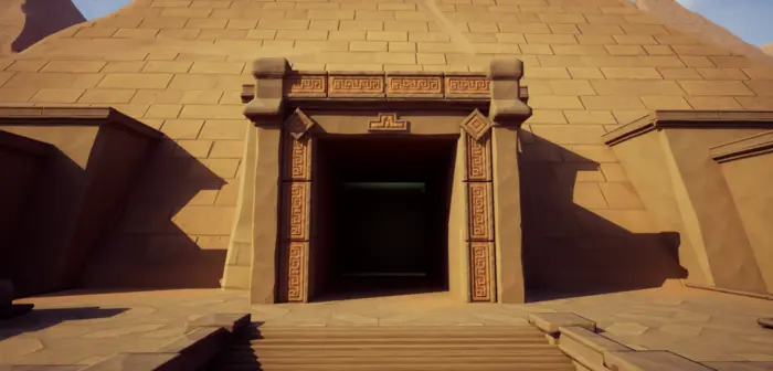
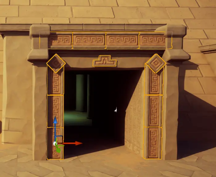
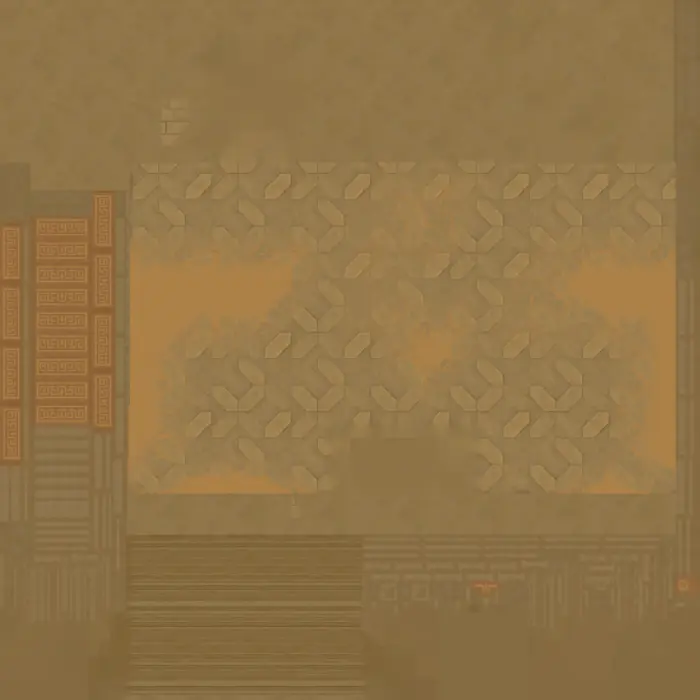
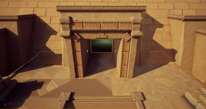
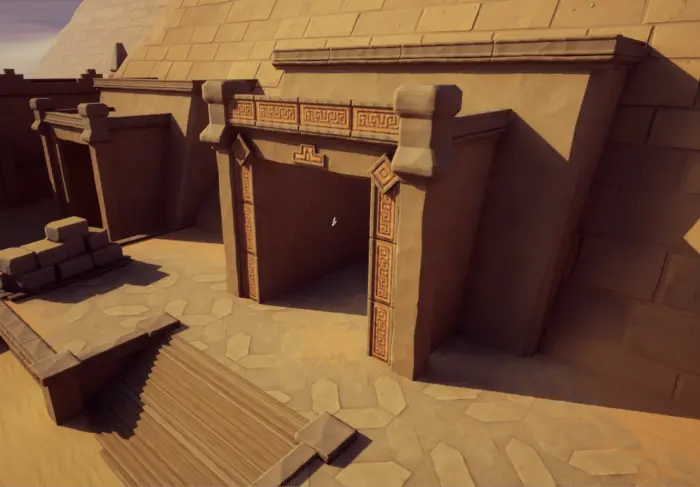
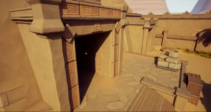
This is the asset we are going to work on. Each squiggly patterned ornament is its own object and we want to aggregate everything together into one draw call.
Solution
Our Unreal Engine plugin has a concept called stand-in. Stand-ins allows you to replace a group of objects with a proxy. Stand-ins can be used to solve issues related to draw calls, overdraw and poly count. In our case we'll just focus on draw calls.
Stand-in
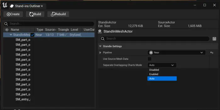
First bring up the Stand-in window by going to menu bar and clicking Window->Standin Outliner. Then select all objects we want to be part of the stand-in and click Create in the top bar of Stand-ins Outliner window.
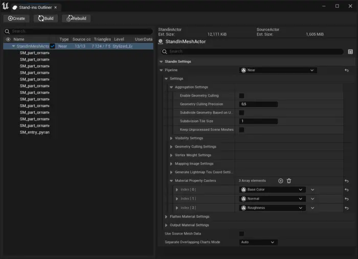
We are going to use the Near pipeline which corresponds to our aggregation pipeline. The other alternative, Far, corresponds to our remeshing pipeline. Far as name implies is for objects we do not expect to view very close. One reason for this is that it does not reuse UV space as the aggregation pipeline do. The aggregation pipeline leaves the surface of the mesh untouched so the player will not notice any difference, while remeshing simplifies the meshes topology. For more discussions on if aggregation or remeshing is right for your use case read our blog about evaluating the best method for proxy creation.
We want to optimize draw calls by merging all materials into one. This is done by adding material casters to our pipeline. We add for the following channels.
- Base Color
- Normal
- Roughness
In our Unreal Engine plugin we have already set the correct settings for casting the different channels so we do not have to do anything more then that. It is worth knowing that only the parts of the texture referred to by the model will be included in the generated atlas. We can specify how large the aggregated texture atlas should be in Mapping Image Settings → Output Material Settings → Texture Width / Texture Height. In our case we set it to 2048x2048 pixels.
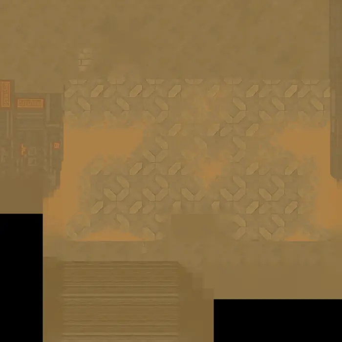
We can generate a stand-in mesh by clicking Build in the Stand-in outliner window. After generating, let us inspect the generated texture. A huge portion of the texture consists of the tile floor where a sand and brick texture has been blended together using vertex colors. We can also see several copies of the squiggly ornament textures that we had around the door frame. As our material only consists of a set of textures it is not possible to address the portion of the texture dedicated to the floor, but we can solve that we have multiple copies of the ornament texture.
Debug intermediary textures
We can start by asking us the question of how can Simplygon understand all materials we can set up in Unreal Engine's material system.
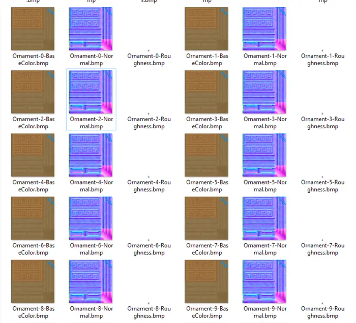
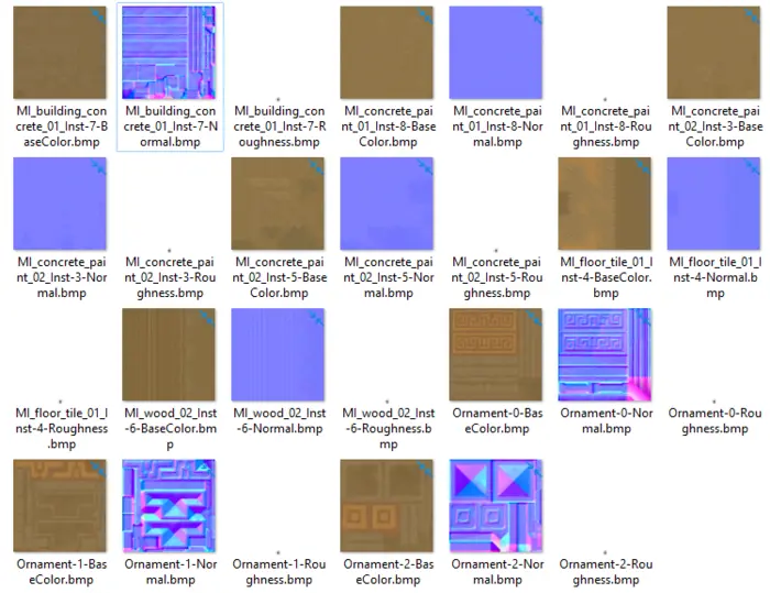
The answer is that we flatten the materials before sending then in to Simplygon. We can view these flattened textures by typing ‘MaterialBaking.SaveIntermediateTextures 1’ into the console and rebuilding the stand-in. The flattened textures can then be found in ‘[ProjectFolder]\Intermediate\MaterialBaking’. We get one texture per model per material channel we use for baking.
We can see that we get multiple copies of the Ornament texture. Each instance of the ornament mesh has its own set of textures. This is the root of our UV reuse issue.
The observant reader might realize that if we export a set of textures per model when we will only be able to reuse UV space between different instances of the same model. This is correct as due to how texture baking works we will not be able to detect that the same texture has been used on different models.
Separate overlapping charts mode
We introduced a new way of controlling if material UVs should be overlapped or not in Simplygon 10.2 for Unreal Engine 5.1+. It is a flag called SeperateOverlappingChartsMode. It can be found both in stand-ins but also LOD Recipes.
Per default it is set to Auto, which was the default behaviour before we introduced the flag.
In auto mode it analyses the material and detect if it contains any node which requires that the baked texture has unique UVs. It uses Unreal Engine's FMaterialUtilities::AnalyzeMaterial to check if the material refers to vertex colors, absolute world position and other nodes which can make texture baking different between instances of the same mesh.
Let's try to force overlapping charts by setting SeperateOverlappingChartsMode to Disabled. We then rebuild our stand-in. If we look at the generated texture we get only two set of ornament textures. This is expected as the source asset actually has that texture two times, one for front side and one for back side. We get some other strange artifacts on floor part of the texture.
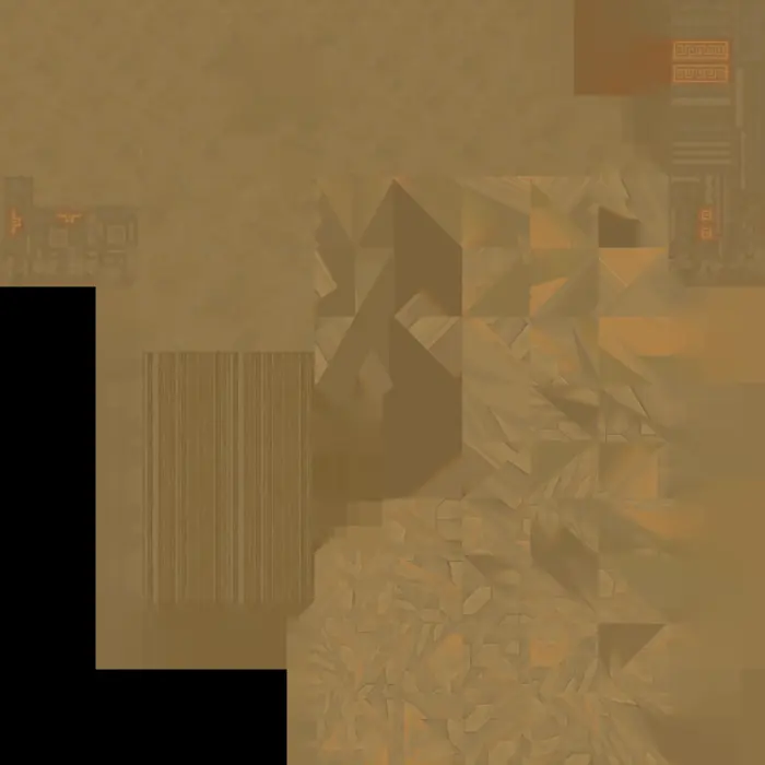
If we inspect the asset in editor we can see that something is clearly wrong. The stand-ins ornaments seems fine, but the floor is a mess.
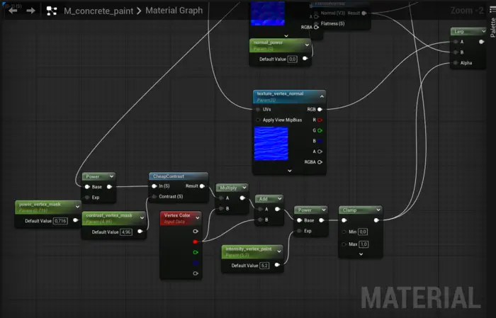
The reason why the floor is a mess is because we now force overlapping UVs if the original UV coordinates are the same. But in this case same UV coordinates does not mean that the texture output will be the same. Let us inspect the floor's material. We can see that it is using vertex colors to blend between two different textures. The square shapes we see is the texture tiling.
So what we can learn from this is that SeperateOverlappingChartsMode can in some cases solve your asset's UV overlapping issues. It would have solved our problems if we only wanted to create a stand-in for the ornaments. But in our case it did not work completely.
There is another case where SeperateOverlappingChartsMode can be useful to know of. If you have an asset where the Auto mode fails to detect that the UVs need to be unique it is possible to force unique UV coordinates by setting it to Enabled.
Fix material causing chart separation
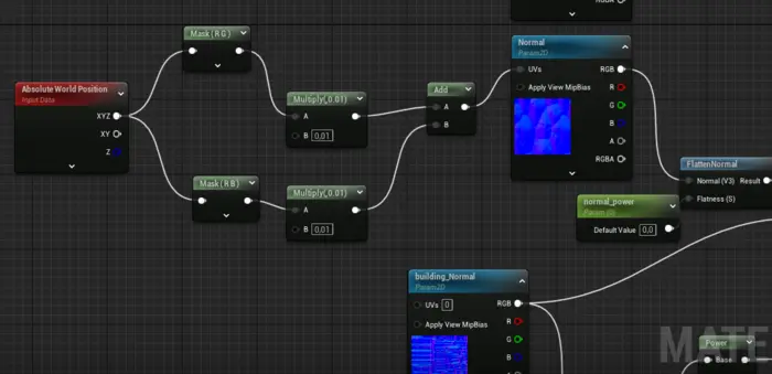
We are now going to dig deeper and address the core of our issues, that the material for our border does not allow us to reuse the same UV space. If we look into the material for it we can quickly find that it use Absolute World Position to put a normal noise texture on the objects. As we said above, if this node is referred to in the material it has to generate unique UVs for our stand-in as we can not be sure the output texture on every instance of the object is the same.
To solve this we need to figure out an alternative way of expressing this normal noise effect and separating out Absolute World Position node causing the UVs to not overlap with a MaterialProxyReplace node. In our case using UV0 works good enough. We add a MaterialProxyReplace node and plug the TexCoord[0] node that should be used during material baking into MaterialProxy and the sub graph using Absolute World Position into Realtime.
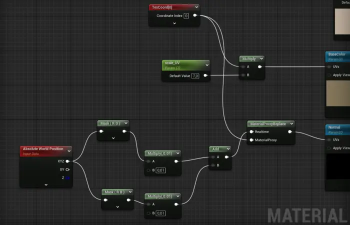
In our example changing from Absolute World Position to TexCoord[0] had a tiny visual impact on the final texture. There are other cases where out Vertex Color or Absolute World Position are only used for visual effects, for example wind animation. In those cases it should make no visual difference in the baked texture.
It is also worth pointing out that some material nodes does not work well with material flattening. If you experience a black output texture this can be the issue. These can as well be separated out with a MaterialProxyReplace node.
We save our changed material. Before rebuilding the stand-in we'll also set SeperateOverlappingChartsMode back to Auto.
Result
After changing the ornament's material so it does not refer to Absolute World Position we get the following intermediary texture output. We now only get one set of texture for the ornament.
Now let's compare in the editor. In our case we changed the normal texture on the squiggly ornament so we expect a slight variation there. But the player will never know that and the stand-in looks like it fits perfectly into our game. We can also see that the vertex blended floor looks correct in the stand-in.
Stand-in
Original
Lastly let us look at the baked texture. As we hoped we only get one pair of texture for the ornament and the vertex blended floor texture looks correct.